
Optical unit, light processing unit, light processing method, illumination unit and image generation unit

a technology of illumination unit and optical unit, applied in the direction of color photography, spectral modifiers, optical signalling, etc., can solve the problem of present parasitic radiational noise called “speckle” and achieve the effect of reducing parasitic radiational noise and high yield

Inactive Publication Date: 2007-10-04
SONY DEUT GMBH
View PDF20 Cites 40 Cited by
  • Summary
  • Abstract
  • Description
  • Claims
  • Application Information

AI Technical Summary

Benefits of technology

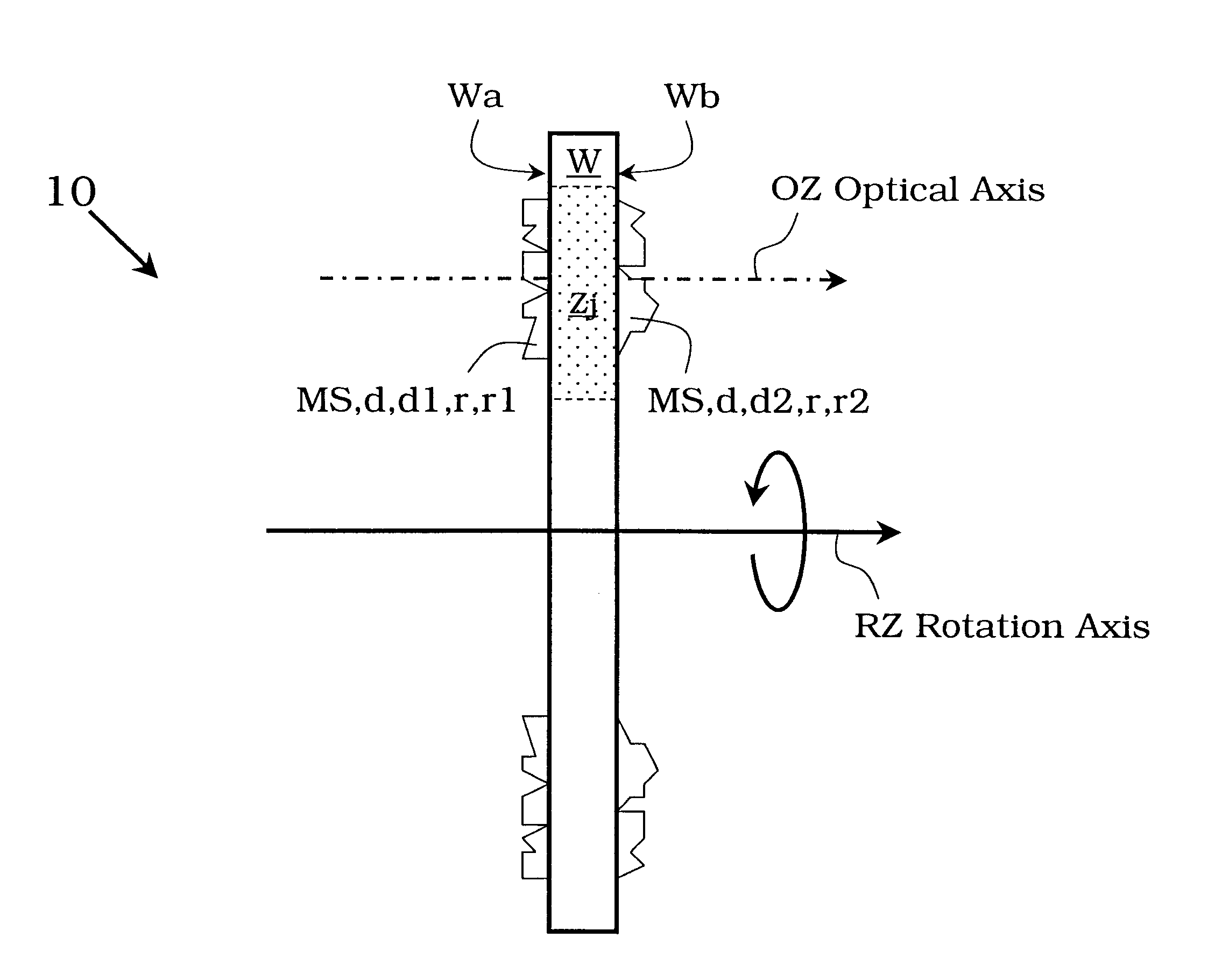
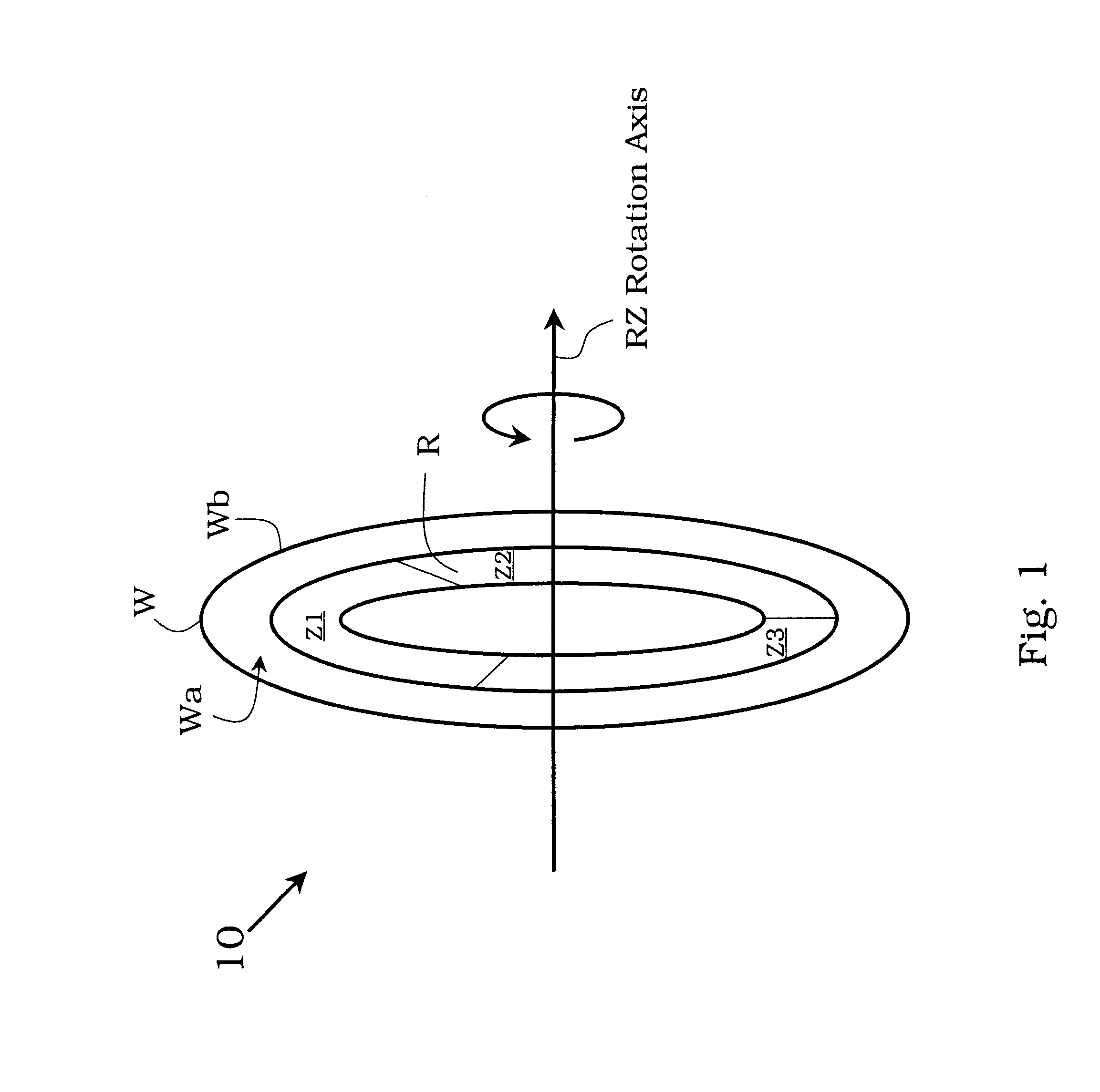
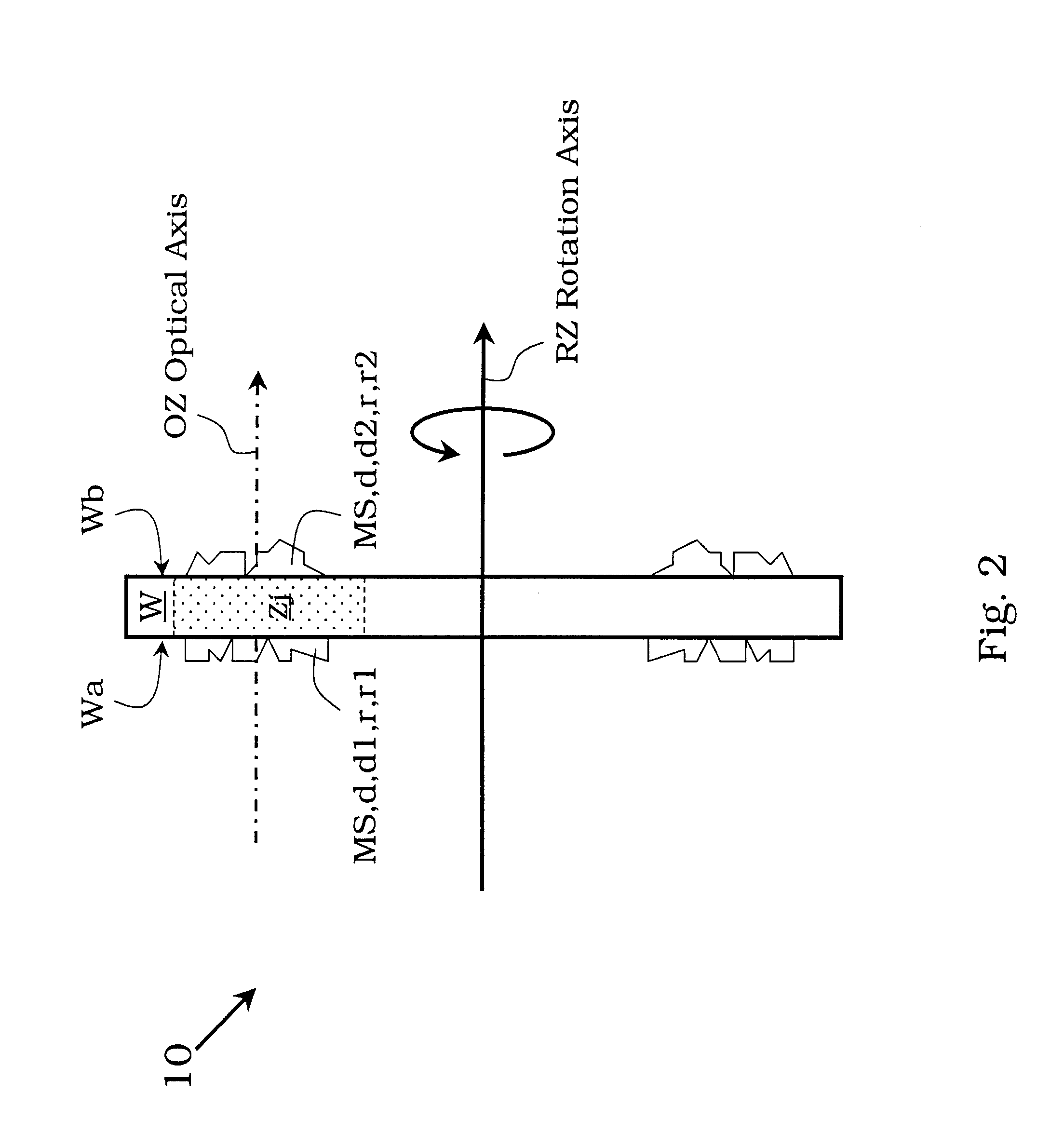
[0003]The present invention provides a light processing method and optical unit, an illumination unit as well as an image generating unit which are using a primary generated illumination light having a comparable high yield and which at the same time can be operated and employed with a reduced parasitic radiational noise. The object underlying the present invention is achieved by a light processing unit comprising a transparent colour wheel to be rotated around an axis and having a front face and a back face, at least one of said faces being provided with a micro-structure on said respective face designed to deflect, diffuse and redistribute light impinging on said front face uniformly such that light beams exiting said back face are oriented along an optical axis.
[0004]In order to display colour images, respective devices such as projectors need to recombine several monochromatic or single colour images. These elementary images are produced in accordance with the prior art by micro-displays that have to be illuminated uniformly. When a laser source is involved, parasitic noise called “speckle” is present due to scattering within the system. The present invention realizes the recombination of elementary images, beam shaping and homogenization of several colour channels onto the image formation devices and reduces the speckle due to the use of coherent light sources such as lasers with reduced number of parts that realizes the recombination, in particular by the use of specifically designed colour wheel.
[0007]Due to the individual orientation, shaping and redistributing of light at the location of one element, the colour wheel, the invention combines in one the functionalities usually provided by three to four elements, for example the rod, the colour wheel, a primary reflector and a moving diffuser. When combined with synchronized laser sources, the invention has the advantage not to generate losses which are common with colour wheels of the prior art.
[0011]Generally, and at the present state of the technology, it may be advantageous to provide two structures for beam shaping and light redirecting, one on each face of the colour wheel, namely e.g. a refractive micro-prism on one side and a hologram on the other side of the colour wheel. This solution helps to balance any possible deviation between the respective functions of the two structures resulting in less stringent fabrication constraints. Also the diffuson functionality can be distributed between the two surfaces of the colour wheel.

Problems solved by technology

When a laser source is involved, parasitic noise called “speckle” is present due to scattering within the system.

Method used


Image

  • Optical unit, light processing unit, light processing method, illumination unit and image generation unit
  • Optical unit, light processing unit, light processing method, illumination unit and image generation unit
  • Optical unit, light processing unit, light processing method, illumination unit and image generation unit

Examples


Embodiment Construction

[0025]In the following description of the invention and embodiments thereof, functional and structural similar or equivalent elements or components will be denoted with the same reference symbols, not in each case of their occurrence a detailed description will be repeated.

[0026]According to one aspect of the present invention, processing optical unit 10 is proposed which comprises a light entrance section E for primary light L1, a light processing unit P comprising a transparent colour wheel element W for processing said received primary illumination light in order to generate processed primary illumination light L1′ thereof as secondary illumination light L2, and a light output section O for providing said secondary illumination L2.

[0027]The term “illumination light L2” as used herein is to be understood to also comprise individual or plural of light fractions or light components, e.g. primary illumination light components L1R, L1G, L1B, pre-processed components L1R′, L2G′, L2B′ o...


PUM


Abstract

For displaying a color image by recombination of several single color images, parasitic noise like speckles due to scattering within the system, in particular when laser light is involved, with the invention a significant improvement with a low number of parts can be realized by use of a color wheel that comprises in radially divided zones refractive elements for redirecting light beams incoming at different impinging angles and redistributing elements, e.g. a hologram, that provide for a defined output beam in an optical axis. The sequence of the individual light processing zones on the color wheel are synchronized with respective laser sources. The invention combines the functionality of plural elements, reduces speckles and avoids losses.

Description

FIELD OF THE INVENTION [0001]The present invention relates to a light processing unit making use of a transparent colour wheel element rotating around an axis, to a light processing method, to an illumination device including a light processing unit and to an image generation unit. More in particular, the invention relates to a display device for colour image making use of colour recombination, light shaping and speckle reduction and to an image display engine making use of the method and such a device.BACKGROUND OF THE INVENTION [0002]Display devices are important for many kind of electronic equipment and customer devices. The technical development in this field focuses amongst others on processes and devices for illumination, image generation and projection. It is, however, a well-known problem that illumination devices may loose a significant amount of primary produced illumination light because of an insufficient adaptation between for instance a broad band light source and resp...

Claims


Application Information

Patent Timeline
IPC IPC(8): F21S8/00
CPCG02B5/32G03B33/08G02B27/0933G02B27/0944G02B27/102G02B27/1086G02B27/126G02B27/48H04N9/3114H04N9/3129H04N9/3152H04N9/3197G03B21/208G03B21/2033G02B26/008
Inventor RIPOLL, OLIVIERKAMM, MARKUS
Owner SONY DEUT GMBH
Learn More