
Conductive connecting members and electrochemical systems

Active Publication Date: 2007-10-04
MORIMURA SOFC TECH CO LTD
View PDF3 Cites 26 Cited by
  • Summary
  • Abstract
  • Description
  • Claims
  • Application Information

AI Technical Summary

Benefits of technology

[0007]However, the present inventors have further conducted a research for stacking larger cells, and have found remaining problems as follows. That is, the amount of warping of the cell may be as large as 1 mm in the stacking of actual large-size cells. Such warping can be absorbed by the deformation of the emboss-shaped portion, so that good electrical connection can be maintained even if the flatness of the cell is deteriorated. However, the emboss-shaped portion has a large spring constant owing to its shape, so that there is a large difference of the stresses generated at positions where the emboss-shaped is flattened and not flattened. In the case that the warping of the electrochemical cell is increased, the emboss-shaped portion would give a large and uneven stress onto the electrochemical cell, so that the cell would be susceptible to destruction.
[0009]An object of the present invention is to provide a conductive connecting member for electrical connection for electrochemical cells, so that the member can follow a relatively large warping and dislocation of the cell to assure the electrical connection and the overload of a stress onto the cell can be prevented when the member follows the warping and dislocation.
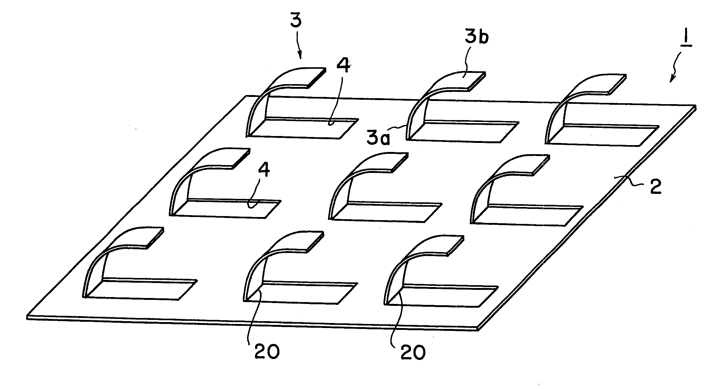
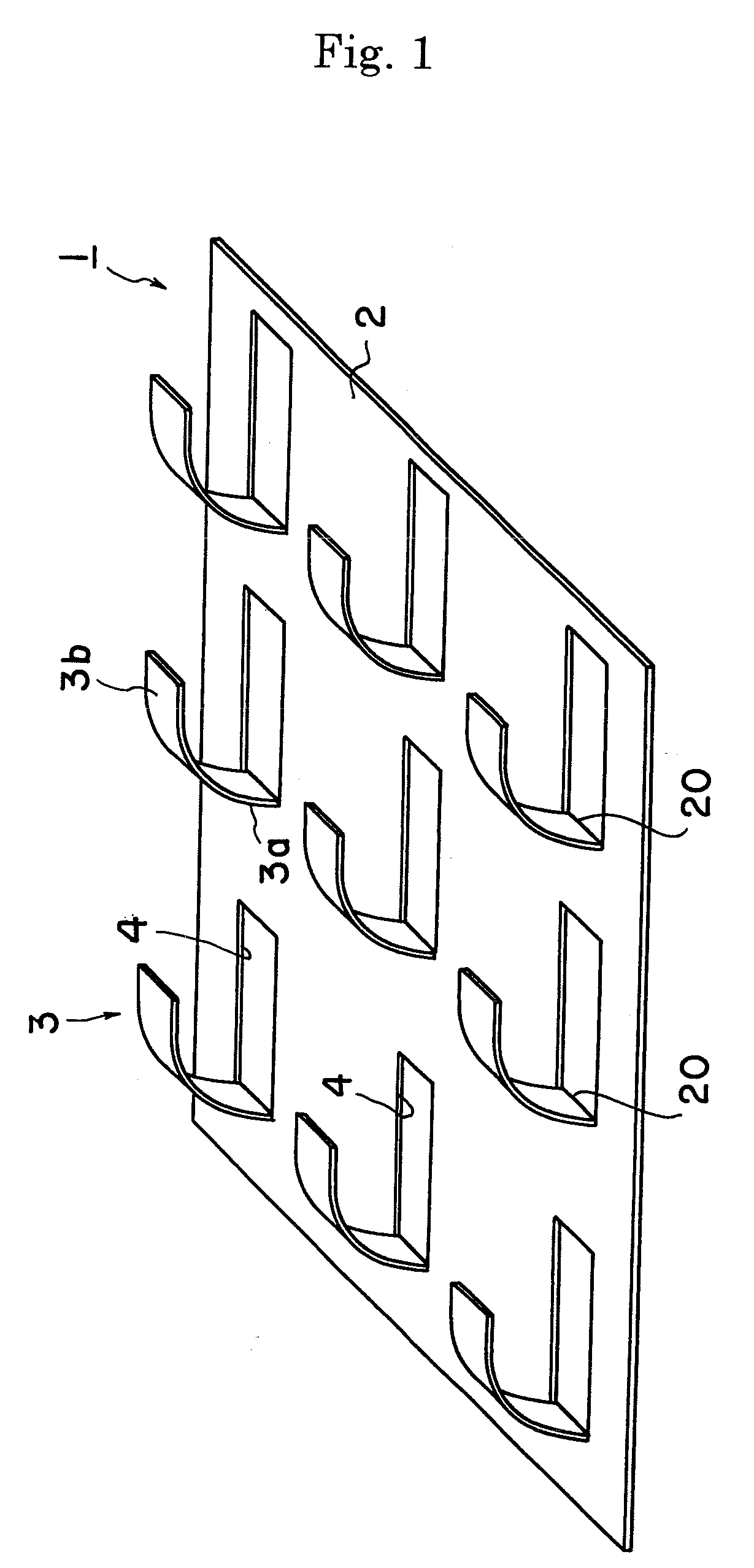
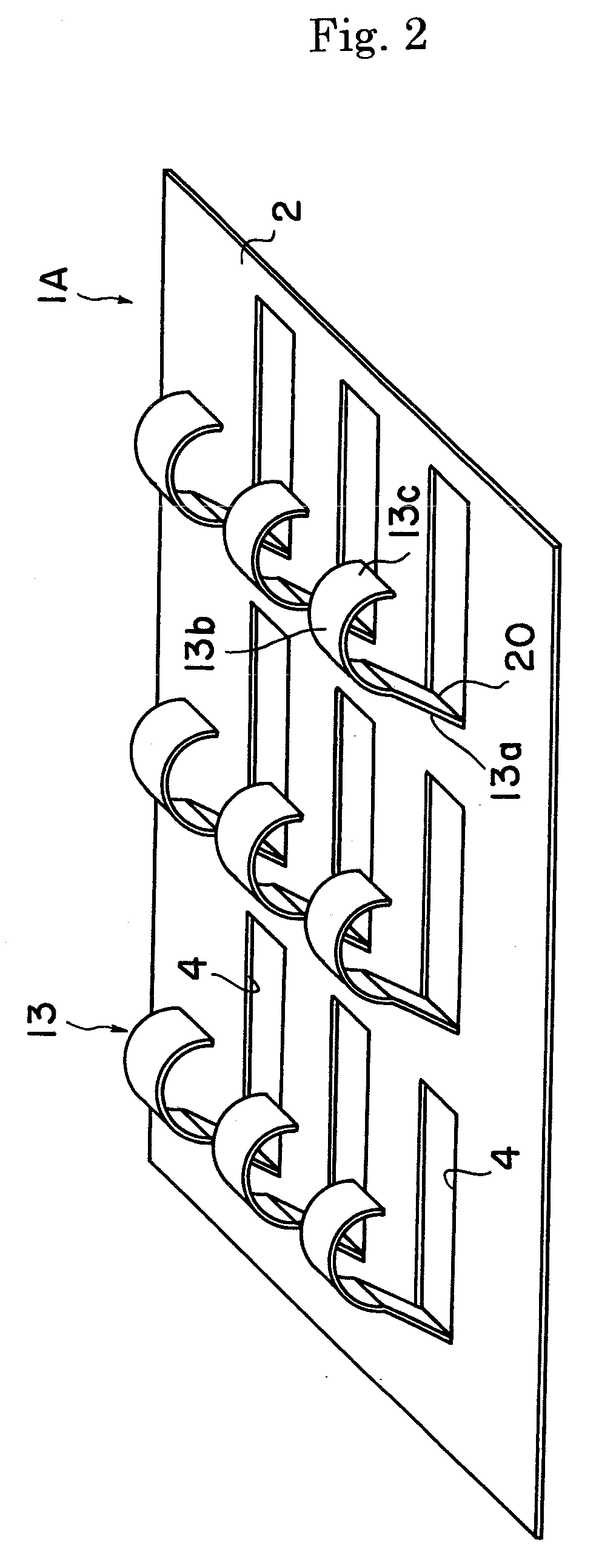
[0012]According to the present invention, the conductive connecting member has a tongue piece protruding from the plate like main part. The tongue piece is contacted with the electrochemical cell to assure the electrical connection. Unlike the emboss-shaped portion, the tongue piece can easily follow larger warping and dislocation. That is, when the size of the electrochemical cell is enlarged, the tongue piece can sufficiently follow a relatively large warping and dislocation of the cell. Moreover, the spring constant to the deformation can be made smaller, so that excessive stress onto the electrochemical cell can be avoided and the destruction of the cell can be prevented.

Problems solved by technology

However, the emboss-shaped portion has a large spring constant owing to its shape, so that there is a large difference of the stresses generated at positions where the emboss-shaped is flattened and not flattened.
In the case that the warping of the electrochemical cell is increased, the emboss-shaped portion would give a large and uneven stress onto the electrochemical cell, so that the cell would be susceptible to destruction.
In this case, the mesh of the emboss-shape could not follow the change of the warping amount, so that the electrical contacts would be reduced to result in a reduction of generation performance.

Method used


Image

  • Conductive connecting members and electrochemical systems
  • Conductive connecting members and electrochemical systems
  • Conductive connecting members and electrochemical systems

Examples


examples

[0052]A solid oxide fuel cell was produced having a substrate of a fuel cell as follows.

(Preparation of a Fuel Electrode Substrate)

[0053]50 parts by weight of nickel oxide powder having an average particle diameter of 1 μm and 50 parts by weight of 8 mol % yttria-stabilized zirconia powder (8YSZ: “TZ-8Y”: supplied by Tosoh Corporation) were mixed and polyvinyl alcohol (PVA) was added as a binder to produce slurry. The slurry was dried and granulated with a spray drier to obtain powder for fuel electrode substrate. The granulated powder was molded by a one-directional press to obtain a disk having a diameter of 120 mm and a thickness of 1.5 mm. Thereafter, the disk was sintered for 3 hours at 1400° C. in air in an electric furnace to obtain a fuel electrode substrate 6a.

(Preparation of Solid Electrolyte Film)

[0054]Water and a binder were added to 8 mol % yttria-stabilized zirconia powder and mixed in a ball mill for 16 hours. The thus obtained slurry was applied on the fuel electrod...


PUM

PropertyMeasurementUnit
Pressureaaaaaaaaaa
Electrical conductoraaaaaaaaaa
Permeabilityaaaaaaaaaa

Abstract

A conductive connecting member 1 is contacted with an electrochemical cell for electrical conduction. The cell has a solid electrolyte film, a first electrode provided on a first face of the solid electrolyte film and contacting a first gas and the first gas, and a second electrode provided on a second face of the solid electrolyte film and contacting a second gas. The conductive connecting member 1 has a plate-like main part 2 and a tongue piece 3 protruding from the main part 2. One end of the tongue piece 3 is connected with the main part 2.

Description

[0001]This application claims the benefit of Japanese Patent Application P 2006-91583 filed on Mar. 29, 2006, the entirety of which is incorporated by reference.FIELD OF THE INVENTION[0002]The present invention relates to a conductive connecting member and a electrochemical system.BACKGROUND ARTS[0003]To produce a generator by stacking separators and solid oxide fuel cells alternately, it is necessary to supply a gas between a separator and the single cell so that fuel or oxidizing gas is supplied to the electrodes of the single cell. At the same time, the single cell and the separator must be electrically connected in series by inserting an electrically conductive connecting member between the separator and single cell. When such connecting member is located in, for example, a fuel gas passage, it must be chemically stable in a reductive fuel gas environment at an operating temperature of the single cell. Further, there must be a gap which the fuel gas is passed. For such reasons, ...

Claims


Application Information

Patent Timeline
IPC IPC(8): B21D28/00H01M8/02
CPCH01M8/0206H01M8/0247H01M8/0256Y10T428/12361Y02E60/50Y02E60/525H01M2008/1293
Inventor RYU, TAKASHITAKASE, NAOYA
Owner MORIMURA SOFC TECH CO LTD
Learn More