

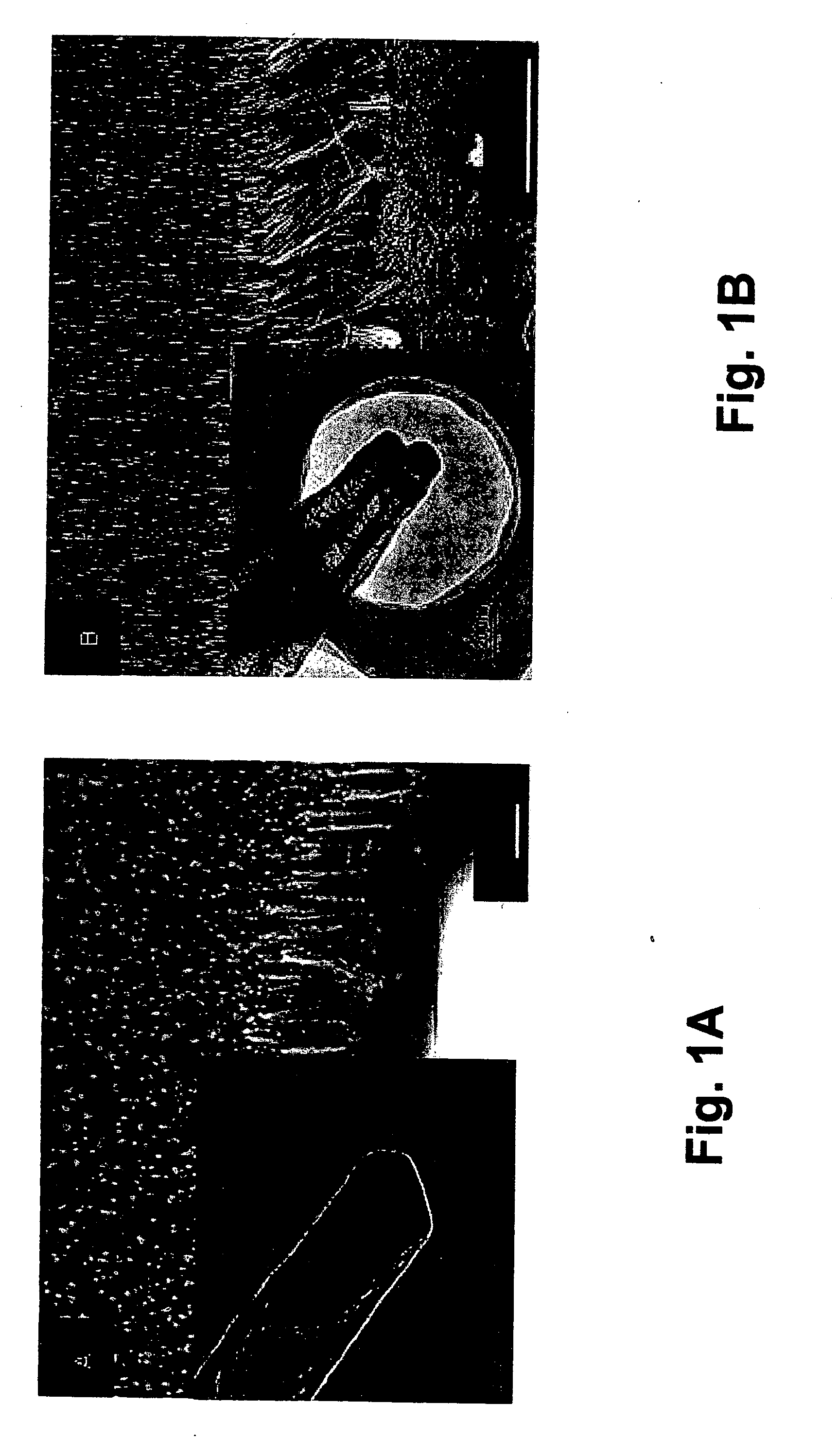
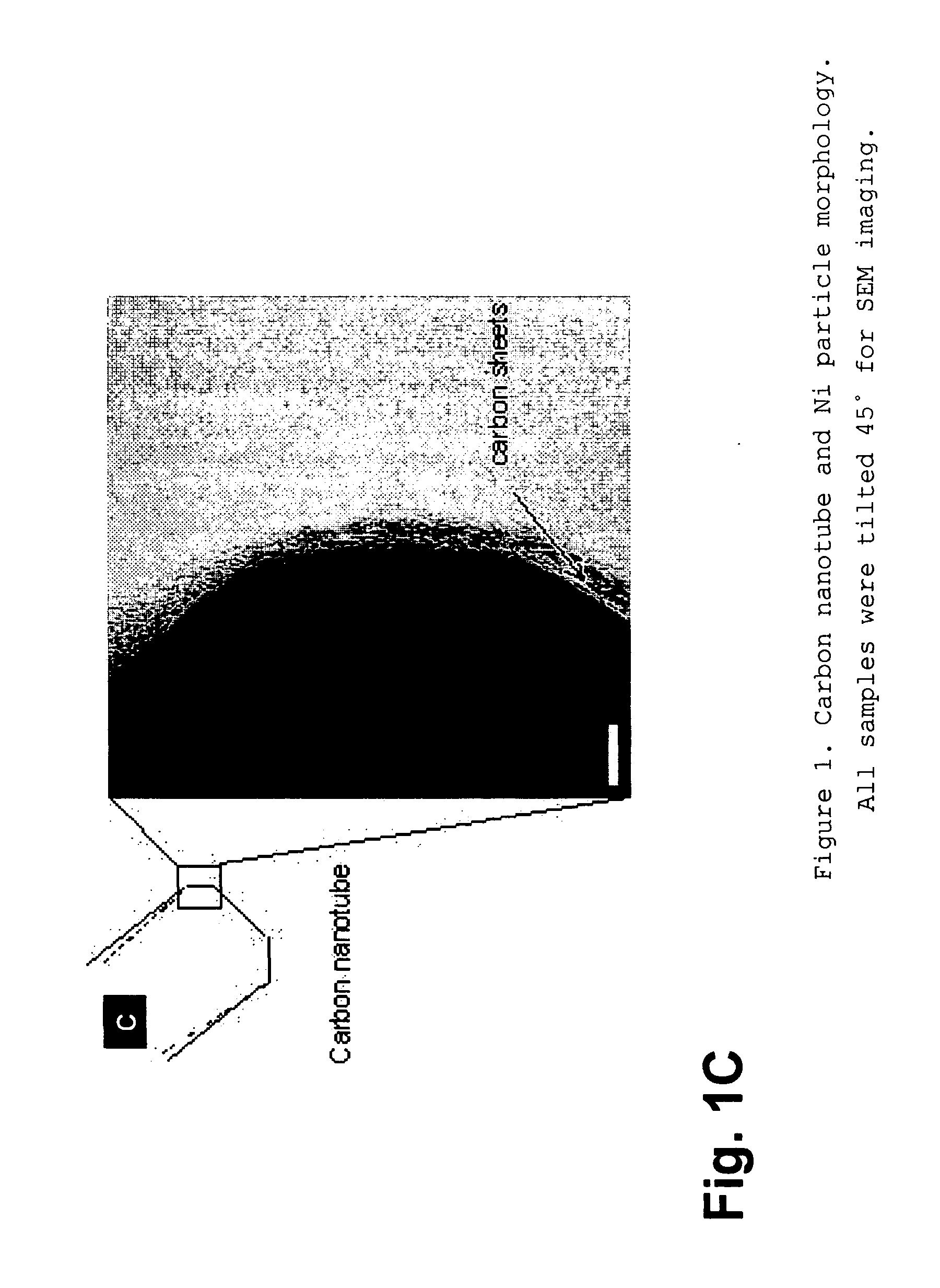
Nanospearing for molecular transportation into cells
a molecular transportation and nanotechnology, applied in the field of nanomaterials, can solve the problems of significantly negatively affecting neither cell function nor cell viability, and achieve the effect of convenient and reliable attachment of biomolecules, high efficiency transfection, and significant negatively affecting cell function and cell viability
- Summary
- Abstract
- Description
- Claims
- Application Information
AI Technical Summary
Benefits of technology
Problems solved by technology
Method used
Image

Examples
example 1
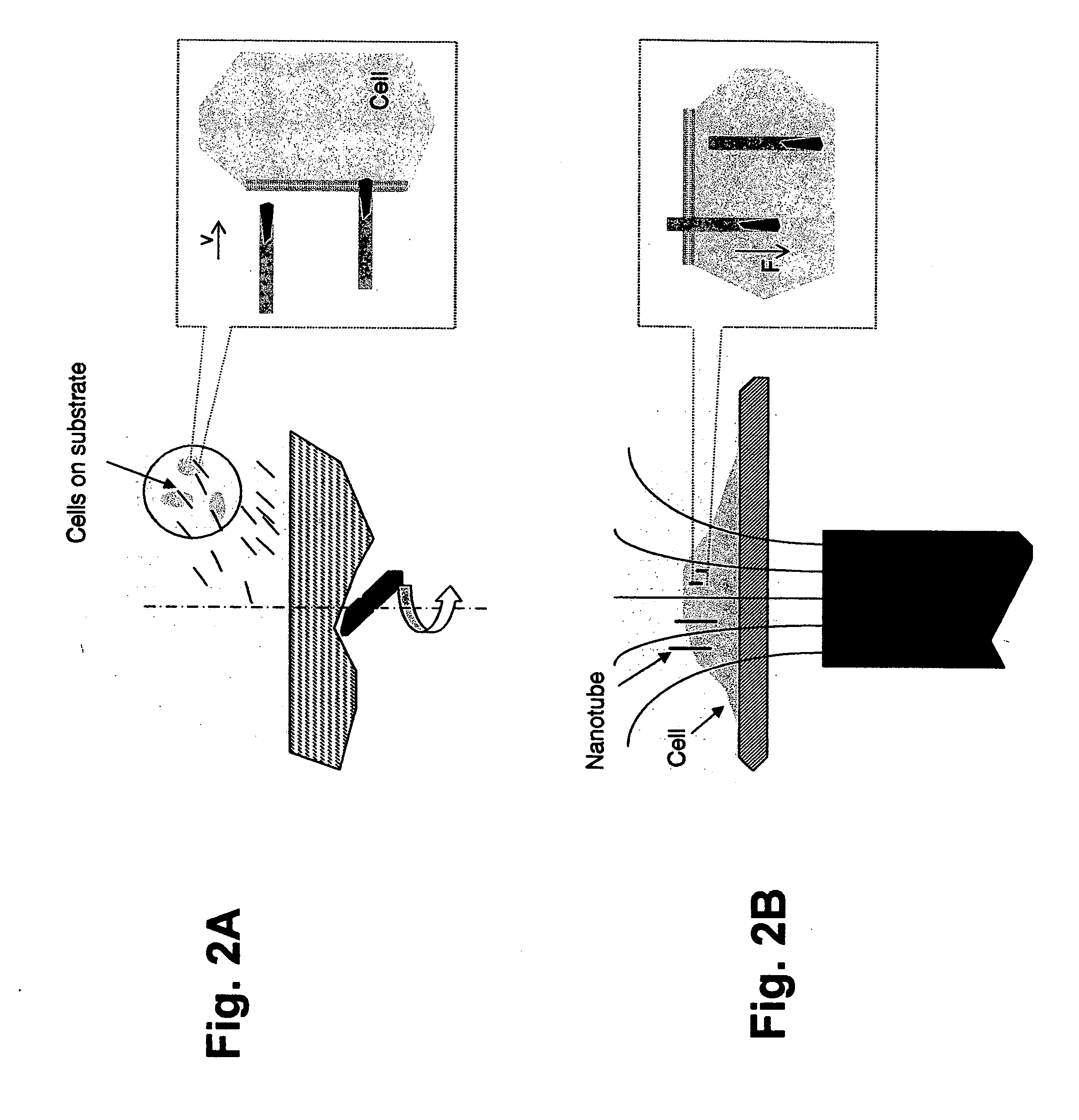
[0118] In one embodiment of the present invention, cells were dispersed on poly(D-lysine)-coated substrates, (e.g., grids and cover slips). A beaker, containing 10 ml of serum-free Dulbecco's Modified Eagle Medium supplemented with magnetically-drivable nanotubes (0.1 pM), was placed on a magnetic stirrer (Fisher Scientific) at room temperature. The substrates were then picked up with tweezers and vertically placed into the beaker, with the cells facing in the direction of the “incoming” nanotubes. The speed of the stirrer was set at 1,200 r.p.m. so as to cause the nanotubes to be driven spear-like into the stationary target cells. Thereafter, in order to enhance the nanospearing with a static magnetic field, the cell substrates were transferred to a cell dish, and the cell dish was laid on a Nd—Fe—B permanent magnet. An adaptor, comprising grooves machined on its surface, was sandwiched between the cell dish and the Nd—Fe—B permanent magnet so as to produce a stray field with high ...
example 2
[0119] MCF-7 cells were subjected to nanospearing in accordance with the two-step nanospearing procedure discussed above. The typical membranes of MCF-7 cells that were cultured on a grid in this experiment are shown in FIGS. 3A and 3B. FIG. 3A is an image showing the cells without nanospearing, and FIG. 3B is an image showing the cells with nanospearing. Scale bars in FIGS. 3A and 3B are 1 μm and 500 nm, respectively. The dashed ovals seen in FIG. 3B mark the nanotubes in the membrane.
[0120] After comparing SEM images of the cell membranes subjected to various combinations of nanospearing conditions, it was seen that the microvilli in the membranes of the cells depicted in FIGS. 3A and 3B have the same site density, which is 15 microvilli / μm2.
[0121]FIG. 3C illustrates the spearing efficiency of cellular membrane penetration for cells that were nanospeared under various magnetic field combinations. The process in which cells were subjected to spearing for three minutes in a rotati...
example 3
[0124] In another example, the magnetically-drivable nanotubes were grown aligned on a 2×2 cm silicon wafer. Subsequently, they were scraped off and suspended in 5 ml of ethyl alcohol, resulting in an estimated concentration of approximately 1 pM. The suspension was then centrifuged at 10,000 g at room temperature for ten minutes. Next, the supernatant was discarded and the nanotubes were resuspended in 0.5 M HNO3 to functionalize the nanotube surface with carboxyl groups, as shown in FIG. 4A. The container was then placed overnight near a Nd—Fe—B magnet.
[0125] Looking next at FIG. 4B, the nanotubes are attached to the wall of the beaker closest to the magnet, as indicated by the red oval. The nanotubes were collected and washed three times with deionized water by repeating the centrifuge and resuspension cycle. These nanotubes were then stored in 5 ml of ethyl alcohol at room temperature.
[0126] The nanotubes extracted from 1 ml of the stock were mixed with 5 μg of plasmid and 10 ...
PUM
 Abstract
Description
Claims
Application Information