Failure detection apparatus for variable valve timing and lift control system of internal combustion engine

a technology of failure detection and control system, which is applied in the direction of braking system, process and machine control, instruments, etc., can solve the problems of erroneous detection, difficult to perform accurate failure detection, and the decline of sensing accuracy

Inactive Publication Date: 2007-10-11
HONDA MOTOR CO LTD
View PDF6 Cites 25 Cited by
  • Summary
  • Abstract
  • Description
  • Claims
  • Application Information

AI Technical Summary

Benefits of technology

[0006] However, the technique according to the Japanese Patent No. 2943042 tends to cause erroneous detection due to stationary deviations of the seating time caused by individual differences such as initial failure and degradation over time of the sen...

Problems solved by technology

However, the technique according to the Japanese Patent No. 2943042 tends to cause erroneous detection due to stationary deviations of the seating time caused by individual differences such as initial failure and degradation over time of the sensor for detecting seating sound.
If, in consideration of such stationary deviations, the high-level state of the pulses A and B is extended, the sensing accuracy will decline due to the effect of noise, making accurate failure detection difficult to perform.
Further, it is difficult to apply the techniqu...

Method used


Image

  • Failure detection apparatus for variable valve timing and lift control system of internal combustion engine
  • Failure detection apparatus for variable valve timing and lift control system of internal combustion engine
  • Failure detection apparatus for variable valve timing and lift control system of internal combustion engine

Examples


Embodiment Construction

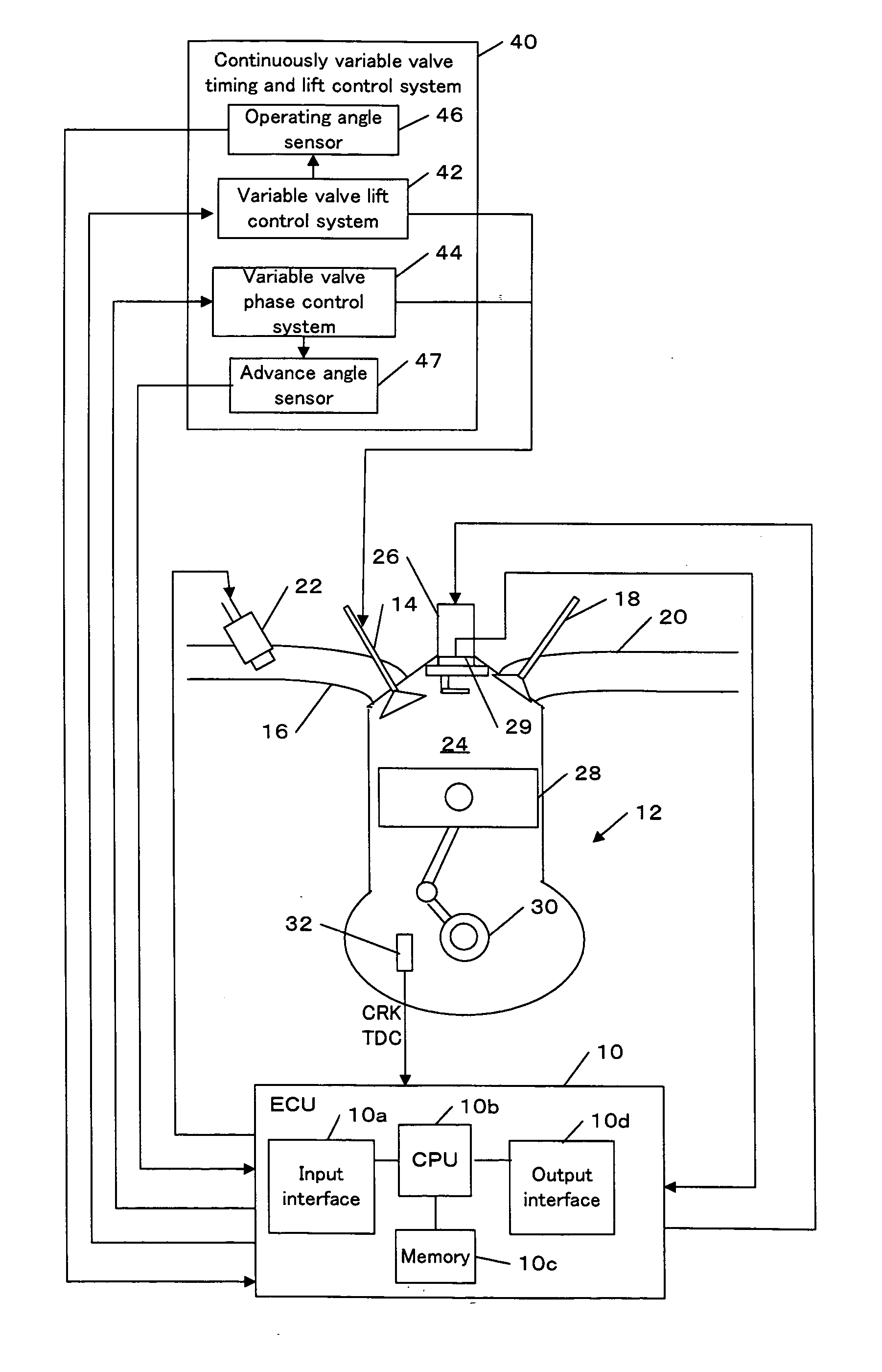
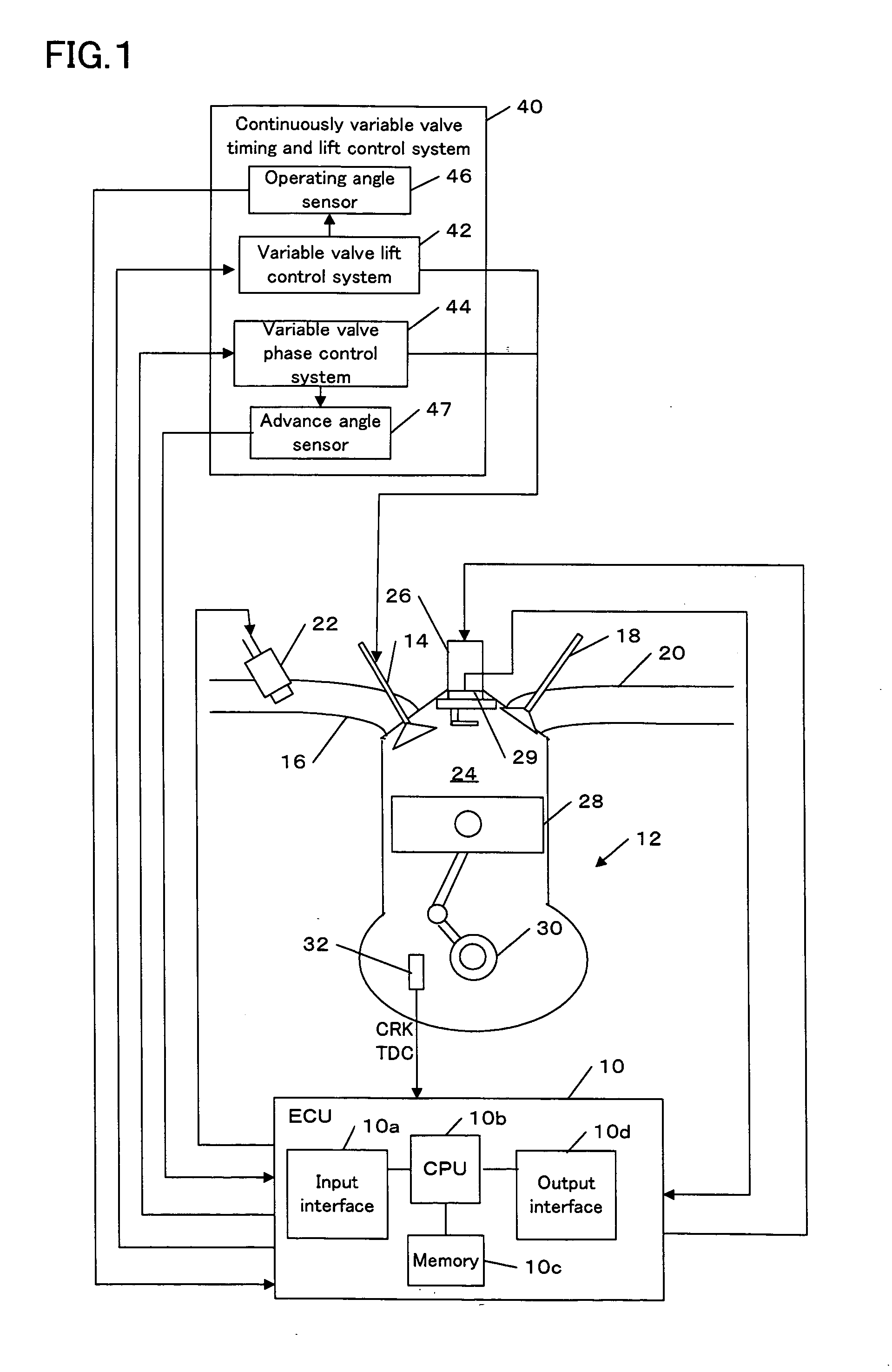
[0028] Next, embodiments of the present invention will be described with reference to drawings. FIG. 1 illustrates a general configuration of an internal combustion engine (hereinafter referred to as an engine) and its control apparatus, according to one embodiment of the present invention.

[0029] An electronic control unit (hereinafter referred to as an “ECU”) 10 is a computer comprising an input interface 10a for receiving data sent from respective parts of the vehicle, a CPU 10b for performing calculation to control the respective parts of the vehicle, a memory 10c having a read only memory (ROM) and a random access memory (RAM) for tempory storage, and an output interface 10d for sending a control signal to the respective parts of the vehicle. In the ROM of the memory 10c, programs for controlling respective parts of the vehicle and various types of data are stored.

[0030] The program for the failure detection of a continuously variable valve timing and lift control system accor...


PUM


Abstract

A failure detection apparatus for preventing erroneous detection due to a degradation of a sensor and thereby accurately performing failure detection of a variable valve timing and lift control system is provided. The detection apparatus detects a failure of a variable valve timing and lift control system in an engine. The detection apparatus detects a vibration inside an engine cylinder, extracts the component of seating sound of the valve from the output signal of the sensor, determines an actual seating time of said valve from the component of seating sound, and calculates a target seating time of said valve based on at least one of a requested lift amount, a requested advance angle, and a requested open angle depending on the operating conditions. The detecting apparatus corrects the actual seating time for a stationary deviation between the actual seating time and the target seating time caused by degradation or unevenness of the sensor. The detecting apparatus determines a failure of the variable valve timing and lift control system by comparing the corrected actual seating time with the target seating time.

Description

BACKGROUND OF THE INVENTION [0001] 1. Field of the Invention [0002] The present invention relates to failure detection for a variable valve timing and lift control system of an internal combustion engine. [0003] 2. Description of the Related Art [0004] To achieve improvements in power output and fuel economy (gas mileage), reduction in exhaust emissions, increase in torque at low revolutions, and higher output power at high-revolution / high-load operation of an internal combustion engine, a variable valve timing and lift control system is known which changes the open / close timing and / or the lift amount of the intake / exhaust valve. [0005] Japanese Patent No. 2943042 discloses a technique for performing failure detection of such a variable valve timing and lift control system. In this technique, frequency components associated with seating sound of the valve are extracted from an output of a vibration sensor that detects the vibration of an internal combustion engine for detecting fail...

Claims


Application Information

Patent Timeline
IPC IPC(8): F02D28/00
CPCF01L1/20F01L1/34F01L13/0063F01L2800/14Y02T10/18F02D13/0207F02D35/023F02D2200/025F01L2820/043Y02T10/12
Inventor OKUBO, KATSURAYASUI, YUJISATO, MASAHIROSHINOZAKI, KOICHIRO
Owner HONDA MOTOR CO LTD
Why Eureka
Try Eureka