Heat Exchanger And Method For Manufacturing The Same

a technology of heat exchanger and heat exchanger body, which is applied in the direction of manufacturing tools, soldering devices, light and heating apparatus, etc., can solve the problems of spoiling the function of heat exchanger, penetration of tubes, etc., and achieve the effect of avoiding the damage of the heat exchanger

a technology of heat exchanger and heat exchanger body, which is applied in the direction of manufacturing tools, soldering devices, light and heating apparatus, etc., can solve the problems of spoiling the function of heat exchanger, penetration of tubes, etc., and achieve the effect of avoiding the damage of the heat exchanger

US20070251091A1Inactive Publication Date: 2007-11-01SHOWA DENKO KK

Image

  • Heat Exchanger And Method For Manufacturing The Same
  • Heat Exchanger And Method For Manufacturing The Same
  • Heat Exchanger And Method For Manufacturing The Same

Examples


example 1

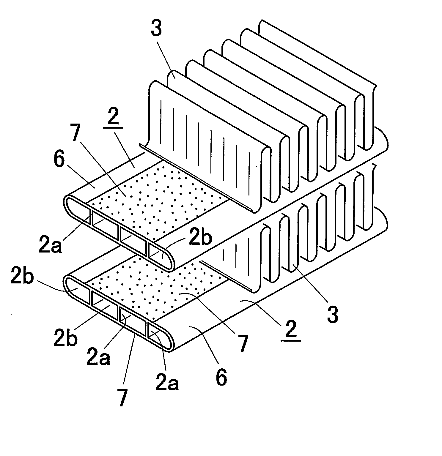
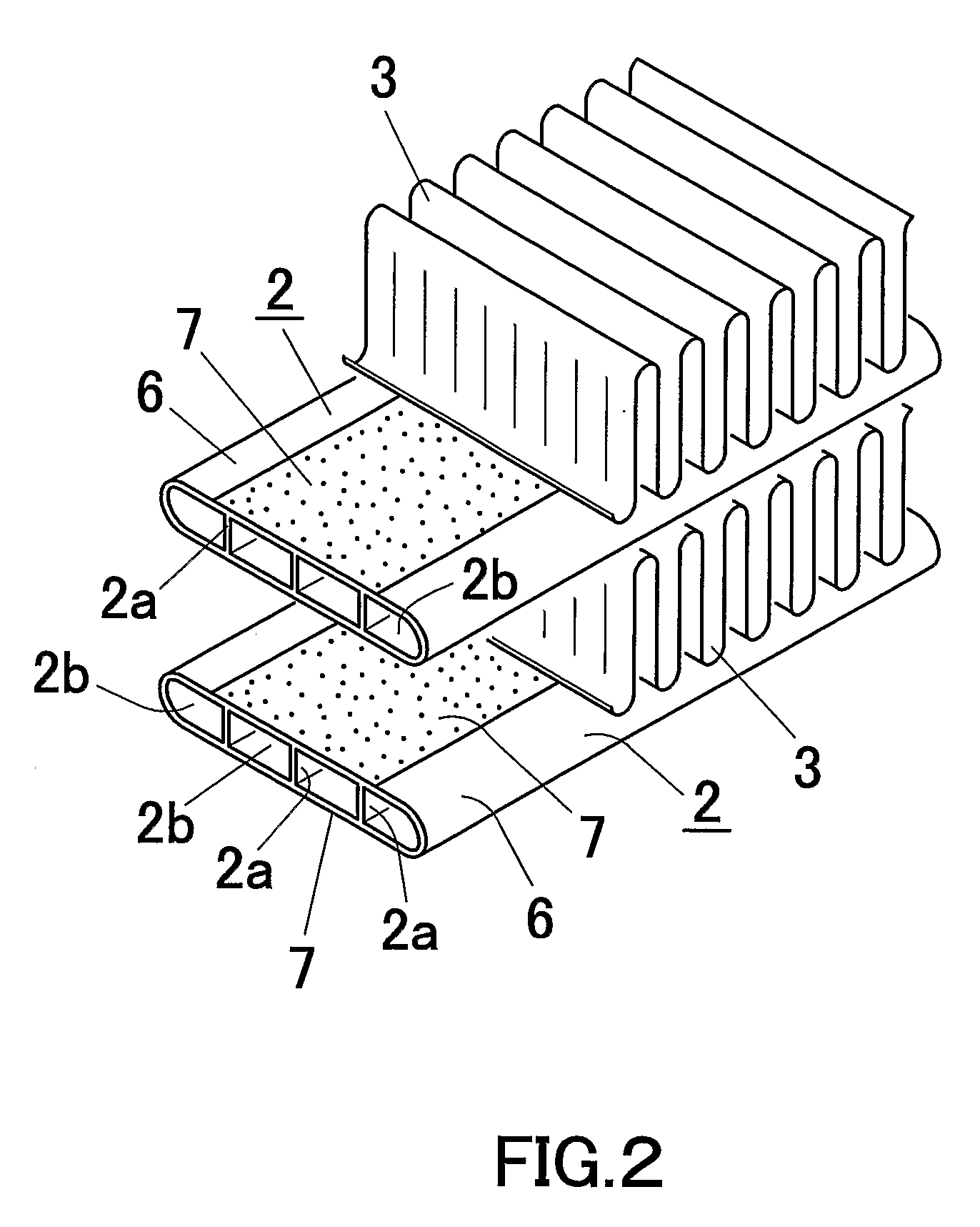
[0094] To upper and lower flat surfaces of an aluminum flat tube continuously extruded from an extruder, brazing material of Al—Si series alloy (Si content: 6 mass %, the balance being Al) was thermally sprayed at a position immediately after the extrusion from a thermal spraying gun (arc-spraying machine) arranged above and below the tube. The extruded flat tube was extruded into a flat tube having a tube width of 16 mm, a tube thickness (height) of 3 mm, a wall thickness of 0.5 mm and four hollow portions by using aluminum alloy (Cu content: 0.4 mass %, Mn content: 0.2 mass %, the balance being Al) under the condition of a temperature of 450° C.

[0095] On the surface of the flat tube 2, flux composite (KZnF3 powder is distributed in paraffin) of KZnF3 / paraffin=50 / 50 (mass ratio) was applied. At this time, the flux composite was applied such that the sprayed amount of KZnF3 became 10 g / m2.

[0096] As the paraffin, paraffin wax (molecular weight of 300) was used. This paraffin exhibi...

examples 2 to 40

[0099] A heat exchanger was manufactured in the same manner as in Example 1 except that various conditions (composition of brazing material, composition of flux composite and applied amount of KZnF3) were set to the conditions shown in Tables 1 to 4.

[0100] The isoparaffin exhibited a property in which 95 mass % thereof evaporated at a temperature of 350° C. when a differential thermal analysis was performed under the conditions of a temperature rising rate of 20° C. / minute and an initial temperature of 25° C. The cycloparaffin exhibited a property in which 95 mass % thereof evaporated at a temperature of 350° C. when a differential thermal analysis was performed under the conditions of a temperature rising rate of 20° C. / minute and an initial temperature of 25° C.

[0101] As butyl series resin, polybutene was used. This butyl series resin exhibited a property in which 95 mass % thereof evaporated at a temperature of 350° C. when a differential thermal analysis was performed under th...


PUM

PropertyMeasurementUnit
temperatureaaaaaaaaaa

Abstract

A method for manufacturing a heat exchanger according to the present invention includes the steps of forming a thermally sprayed layer on a surface of an aluminum tube core by thermally spraying Al—Si series alloy brazing material onto the surface of the aluminum tube core to obtain a tube 2, applying flux composite containing non-corrosive flux showing zinc substitution reaction onto a surface of the tube 2, combining the tube 2 with the fin 3, and brazing the tube 2 and the fin 3 in an combined state.

Description

[0001] This application claims priority to Japanese Patent Application No. 2003-426-408 filed on Dec. 24, 2003 and U.S. Provisional Application No. 60 / 532,906 filed on Dec. 30, 2003, the entire disclosures of which are incorporated herein by reference in their entireties. CROSS REFERENCE TO RELATED APPLICATIONS [0002] This application is an application filed under 35 U.S.C. §111(a) claiming the benefit pursuant to 35 U.S.C. §119(e)(1) of the filing date of Provisional Application No. 60 / 532,906 filed on Dec. 30, 2003, pursuant to 35 U.S.C. §111(b).BACKGROUND OF THE INVENTION [0003] 1. Field of the Invention [0004] The present invention relates to a heat exchanger excellent in corrosion resistance, and its manufacturing method. [0005] In this disclosure, the wording of “aluminum” is used in the meaning including aluminum and its alloy. In this disclosure, “Al” denotes aluminum (metal elementary substance). [0006] 2. Description of the Related Art [0007] The following description sets...

Claims


Application Information

Patent Timeline
01 Nov 2007
Publication
US20070251091A1
IPC
B23P15/26; B23K1/00; F28D1/053; F28F1/12
CPC
B23K1/0012; B23K2201/14; F28D1/05391; Y10T29/49393; F28F19/02; F28F2275/04; F28F1/126; B23K2101/14
Inventors
MINAMI, KAZUHIKO; YAMANOI, TOMOAKI