Multiple pass economizer and method for SCR temperature control

Inactive Publication Date: 2007-11-15
THE BABCOCK & WILCOX CO
View PDF8 Cites 20 Cited by
  • Summary
  • Abstract
  • Description
  • Claims
  • Application Information

AI Technical Summary

Benefits of technology

[0008]It is an object of the present invention to provide a system and method for increasing the outlet temperature of flue gas passing through the economizer by reducing the water flow in selected tubes and/or sections of the economizer without the need to divert feedwater away from the economizer. When these selected tubes or sections are reduced in flow, the remaining sections or tubes in the economizer are overflowed so that the total flow is maintained through the

Problems solved by technology

The increase in water flow in the remaining tubes has a minimal effect on the heat transfer of the remaining tubes, resulting in an overal

Method used


Image

  • Multiple pass economizer and method for SCR temperature control
  • Multiple pass economizer and method for SCR temperature control
  • Multiple pass economizer and method for SCR temperature control

Examples


Embodiment Construction

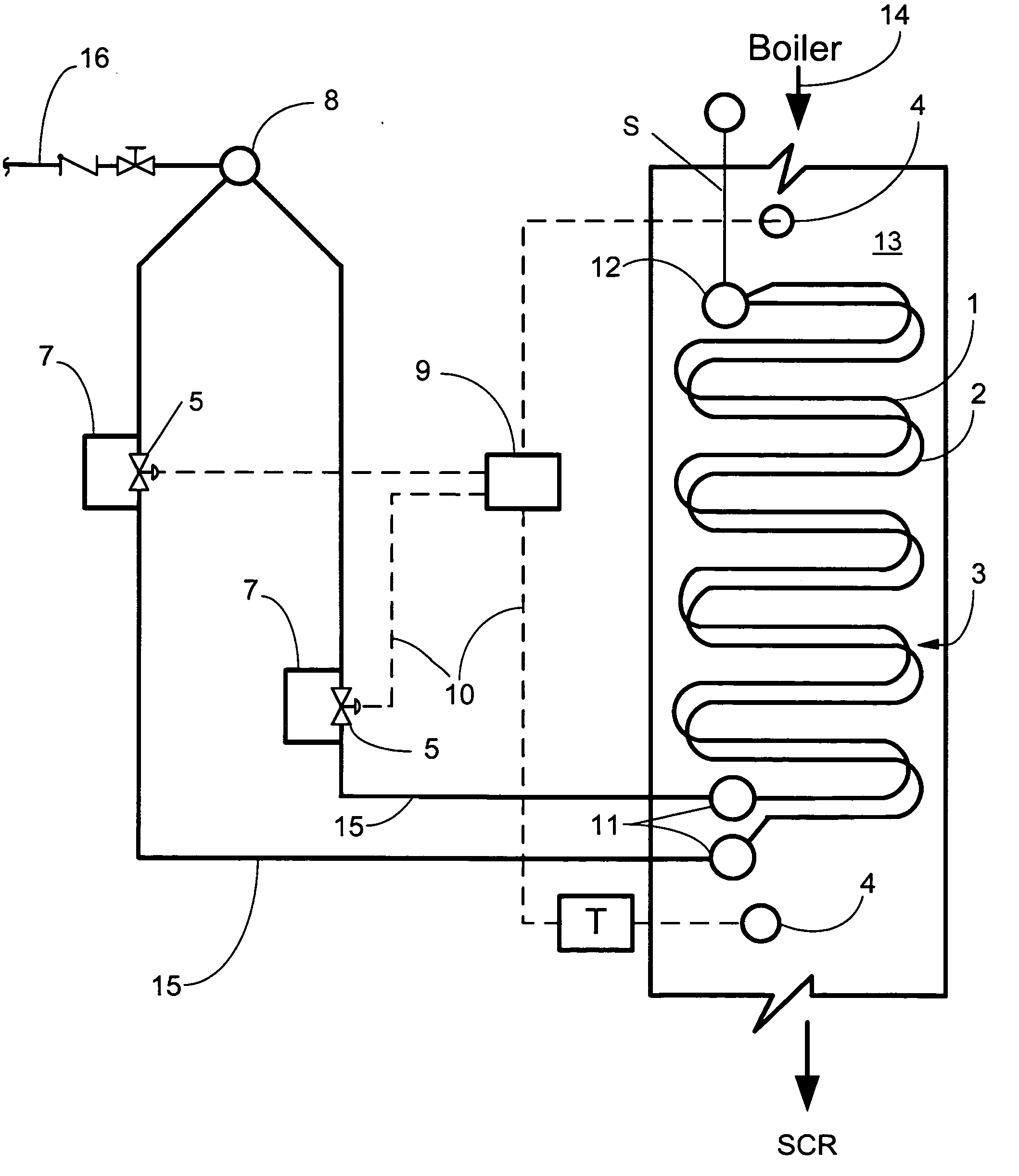
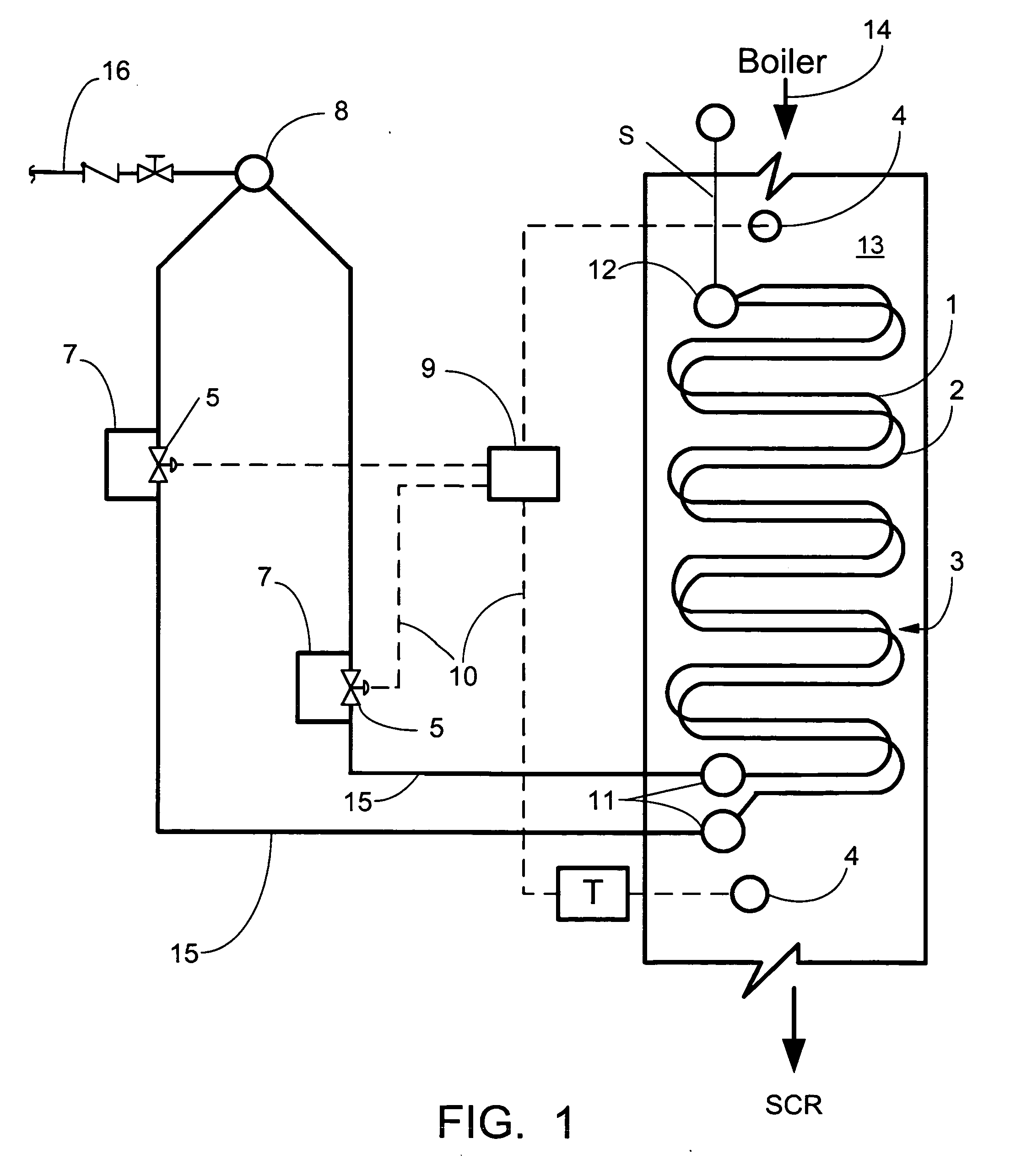
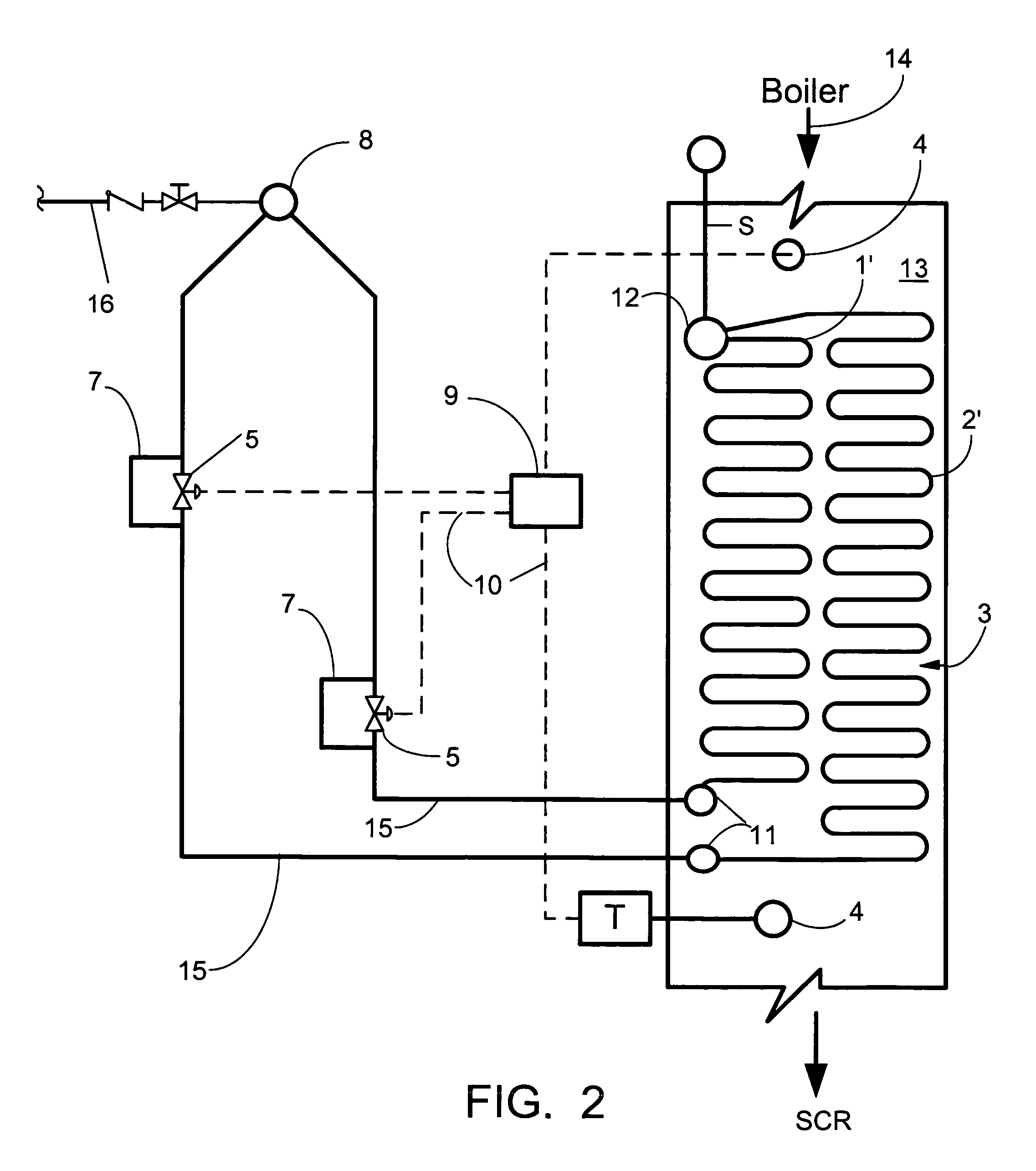
[0025]Referring now to the drawings, in which like reference numerals are used to refer to the same or functionally similar elements, FIG. 1 shows an economizer 3 for receiving flue gas generated by a boiler (not shown), located upstream of and in fluid communication with the economizer 3. As used in the present application and as is known to those skilled in the art, the term boiler is used herein to broadly refer to apparatus used for generating steam and may include both drum-type boilers and those of the once-through type. For a general description of such types of boilers or steam generators, the reader is referred to the aforementioned STEAM 41st reference, particularly the Introduction and Selected color plates, and Chapters 19, 20, and 26, the text of which is hereby incorporated by reference as though fully set forth herein. The economizer 3 includes a flue inlet and a flue outlet, and is located in a convection pass 13 upstream of and in fluid communication with a Selectiv...


PUM


Abstract

A gas temperature control system for maintaining a desired economizer outlet gas temperature across a range of boiler loads comprises a plurality of tubular configurations having surfaces that are in contact with the flue gas. Each tubular configuration, preferably, comprises a plurality of serpentine or stringer tubes arranged horizontally or vertically back and forth within the economizer, and each tubular configuration having a separate feedwater inlet. Heat transfer from the flue gas is accomplished by controlling the feedwater flow rates through the tubular configurations. In a temperature control system having two tubular configurations, the overall heat transfer capacity of the economizer may be reduced to maintain the desired economizer outlet gas temperature during low boiler loads by reducing feedwater flow through one tubular configuration and by overflowing the other tubular configuration, such that total flow of feedwater through the economizer is maintained substantially constant. Feedwater flow rate entering the economizer may be used to engage/disengage the economizer water internal proportion or bias system. Once engaged, the measured feedwater flow to the economizer is used to generate a proportioned or biased flow rate demand signal. The demand signal is then compared to the measured underflow proportioned or biased flow rate. If there is a difference between the demand signal flow rate and the measured flow rate, control valve(s) modulating the proportioned or biased flow is/are adjusted.

Description

CROSS REFERENCE TO RELATED APPLICATION[0001]The present invention is a continuation-in-part of U.S. application Ser. No. 11 / 430,761 filed May 9, 2006.FIELD AND BACKGROUND OF THE INVENTION[0002]The present invention relates generally to the field of Selective Catalyst Reactor (SCR) temperature control and in particular to a system and method for maintaining the combustion or flue gas entering the SCR system at or above the optimal catalytic reaction temperature, even when operating the boiler at reduced loads.[0003]In operating a boiler with a Selective Catalyst Reactor (SCR) system, the effectiveness of the SCR is dependant upon the flue gas temperature entering the catalyst reactor. Most can operate within a temperature range of about 450 degrees F. to about 840 degrees F. Optimum performance may typically occur between about 570 degrees F. to about 750 degrees F. Typically, the desired gas temperature entering the SCR is about 580 degrees F. or greater. At a temperature of about 5...

Claims


Application Information

Patent Timeline
IPC IPC(8): F22D7/00
CPCF22D1/12
Inventor ALBRECHT, MELVIN JOHNBLOSS, JAMES S.FRASCELLO, STEPHEN V.MCGREGOR, MONTE J.
Owner THE BABCOCK & WILCOX CO
Why Eureka
Try Eureka