Method and Apparatus for Producing Synthesis Gas From Biomass

a technology of biomass and synthesis gas, which is applied in the direction of combustible gas production, gasification process details, combustible gas chemical modification, etc., to achieve the effect of reducing the accumulation of by-products and unwanted chemicals in the reaction, reducing the energy consumption

Inactive Publication Date: 2007-11-15
JACOBSEN ANKER J
View PDF12 Cites 18 Cited by
  • Summary
  • Abstract
  • Description
  • Claims
  • Application Information

AI Technical Summary

Benefits of technology

[0031] By conducting the method of the invention in such an alternating manner substantial energy savings are obtained. The energy may be further saved by supplementing the dual biomass reactor apparatus with additional heat storing means for storing heat contained in the flue gasses leaving the common heat storing means. These additional heat storing means are used for preheating the air to be supplied to the combustion means during the following step where the central heat storing means are heated by means of flue gas passing through said means in the opposite direction.
[0032] Furthermore, by alternating the direction of the flow, the build-up of by-products and unwanted chemicals in the reaction can be efficiently minimised. Tar that can form in the biomass reactor is in a gaseous form in the bottom the biomass reactor, where the temperature is highest, but becomes liquefied as the temperature decreases higher up in the biomass reactor. The tar condenses and can clog the system at worst. By alternating the gasification cycle the tar is moved from the top part of the biomass reactor, where it is liquefied, down to the bottom of the biomass reactor and thereafter to the heat storage means. This enhances the thermal and catalytic cracking of the tar in a manner known per se.
[0033] Another advantage of using alternating gas circulation is that in the “colder” end / part of the heat storage means there is a possibility of build-up of soot.
[0034] By alternating the cycles this build-up can be burnt away or efficiently removed. Furthermore, the alternating gas circulation prevents clogging of the system.

Problems solved by technology

However, since such raw materials are available only in limited amounts scientists have lately focussed on the production of synthesis gas from renewable raw materials such as raw materials derived from plants e.g. biomass.

Method used


Image

  • Method and Apparatus for Producing Synthesis Gas From Biomass
  • Method and Apparatus for Producing Synthesis Gas From Biomass
  • Method and Apparatus for Producing Synthesis Gas From Biomass

Examples


example 1

[0071] An apparatus as shown in FIG. 3 is used to produce synthesis gas from spruce chips.

[0072] In the first heating sequence the heat storing means are is heated with the heat generated by the combustion of air and propane for about 40 minutes so as to obtain a temperature of 1150-1200° C. During the first gas production sequence the heated gas is transported through the biomass, for about 3 minutes producing ca. 0.8 m3 / min of synthesis gas. Reheating of the heat storage with part of the produced synthesis gas to 1150-1200° C. takes about 15 minutes. The size of the circulating flow of synthesis gas in the system is about 2 m3 / min.

[0073] The chemical combination of the produced synthesis gas is:

Hydrogen40vol %Carbon monoxide25vol %Carbon dioxide15vol %Methane4vol %Hydrocarbons from C2100ppm.Oxygen1vol %Nitrogen7vol %

example 2

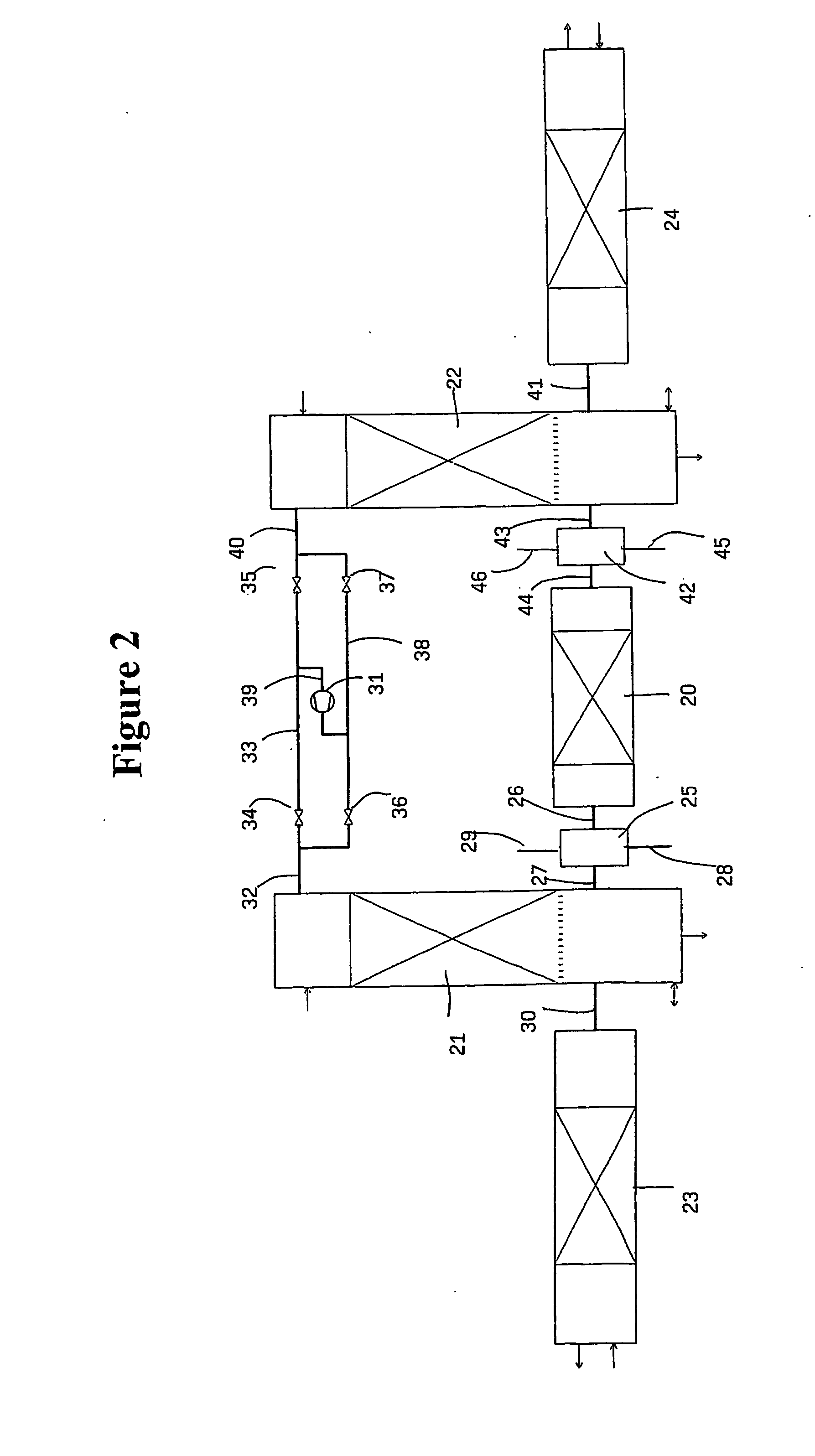
[0074] An apparatus as shown in FIG. 2 is used to produce synthesis gas from spruce chips.

[0075] In the first heating sequence the heat storing means are is heated with the heat generated by the combustion of air and propane for about 40 minutes so as to obtain a temperature of 1150-1200° C. During the first gas production sequence the heated gas is transported through the biomass, for about 3 minutes producing ca. 0.8 m3 / min of synthesis gas. Reheating of the heat storage with part of the produced synthesis gas to 1150-1200° C. takes about 15 minutes. The size of the circulating flow of synthesis gas in the system is about 2 m3 / min.

[0076] The chemical combination of the produced synthesis gas is:

Hydrogen21vol %Carbon monoxide40vol %Carbon dioxide8vol %Methane2vol %Hydrocarbons from C2550ppm.Oxygen1vol %Nitrogen27vol %


PUM

PropertyMeasurementUnit
temperatureaaaaaaaaaa

Abstract

Method and apparatus for producing synthesis gas comprising the steps of combusting (4) a combustible gas to form hot flue gasses (7), passing the flue gasses (7) through heat storing means (1) so as to heat the heat storing means (1) to an elevated temperature, using the heat thus stored to heat biomass (2) to an elevated temperature so as to form synthesis gas, and withdrawing at least part of the synthesis gas formed, wherein following heating of the heat storing means (1) gaseous medium is circulated through the heat storing means (1), the biomass (2) and back to the heat storing means (1). Furthermore computer program product for performing the method of the invention and the use of the produced biogas are disclosed.

Description

BACKGROUND OF THE INVENTION [0001] This invention relates to an apparatus and method of producing synthesis gas from biomass. The invention furthermore relates to computer processing product for performing the method of the invention and the use of the produced synthesis gas. [0002] It is well known to produce synthesis gas which is a mixture primarily consisting of CO and H2 from fossil materials such as coal and crude oils, see U.S. Pat No. 5,637,259. [0003] However, since such raw materials are available only in limited amounts scientists have lately focussed on the production of synthesis gas from renewable raw materials such as raw materials derived from plants e.g. biomass. [0004] Examples of such biomasses are wood, straw, waste paper, municipal solid waste and mixtures thereof. [0005] It is well known that by heating wood materials to a high temperature such as 800° C. under anaerobic conditions the wood materials give off gaseous and liquid substances leaving behind charcoa...

Claims


Application Information

Patent Timeline
Patent Type & Authority Applications(United States)
IPC IPC(8): C10B47/18C10J3/04C10J3/12C10J3/14F28D20/00
CPCC10J3/04Y02E60/142C10J3/14C10J3/721C10J3/723C10J2200/09C10J2300/0916C10J2300/092C10J2300/0946C10J2300/0956C10J2300/1223C10J2300/1253C10J2300/1646C10J2300/165C10J2300/1665C10J2300/1693C10J2300/1807C10J2300/1823C10J2300/1884F28D20/0056Y02E50/18Y02E50/32C10J3/12C10K3/023Y02P20/145Y02P20/129Y02E50/10Y02E50/30Y02E60/14
Inventor JACOBSEN, ANKER J.
Owner JACOBSEN ANKER J
Why Eureka
Try Eureka