Oxygen Sensor and Air/Fuel Ratio Control System

a technology of air-fuel ratio and oxygen sensor, which is applied in the direction of electric control, machines/engines, instruments, etc., can solve the problems of air-fuel ratio control accuracy deterioration, error directly affecting control parameters, and inability to detect and detect errors, etc., to reduce the influence of a rich gas, increase output accuracy, and high diffusion rate

Inactive Publication Date: 2007-11-15
TOYOTA JIDOSHA KK
View PDF8 Cites 12 Cited by
  • Summary
  • Abstract
  • Description
  • Claims
  • Application Information

AI Technical Summary

Benefits of technology

[0074] According to the first aspect of the present invention, the front surface of the exhaust gas side electrode has the reduction means, which reduces the amount of rich gas in the exhaust gas reaching the exhaust gas side electrode so that the output of the oxygen sensor has a sudden output change point at the theoretical air-fuel ratio. This makes it possible to average the exhaust gas reaching the exhaust gas side electrode and reduce the influence of a rich gas having a high diffusion rate. Thus, the oxygen sensor according to the first aspect of the present invention provides increased output accuracy.
[0075] According to the second aspect of the present invention, the surface of the exhaust gas side electrode has a coating layer having a porosity of not higher than 10% as the reduction means. This makes it possible to average the exhaust gas reaching the exhaust gas side electrode with increased certainty.
[0076] According to the third aspect of the present invention, the surface of the exhaust gas side electrode has a coating layer having a thickness of not less than 300 μm as the reduction means. This makes it possible to average the exhaust gas reaching the exhaust gas side electrode with increased certainty.
[0077] According to the fourth aspect of the present invention, the cover having vent holes is used as the reduction means. The vent holes are adjusted so that the exhaust gas flow rate prevailing at the surface of the coating layer is not higher than 1 / 10 the exhaust gas flow rate prevailing outside the cover. This makes it possible to average the exhaust gas reaching the exhaust gas side electrode with increased certainty.
[0078] According to the fifth aspect of the present invention, the output of the air-fuel ratio sensor on the upstream side is corrected in accordance with the output of the oxygen sensor, which is positioned downstream of the three-way catalyst, and the air-fuel ration is controlled in accordance with the corrected output of the air-fuel ratio sensor. The oxygen sensor on the downstream side includes the reduction means, which ensures that the ratio of the amount of exhaust gas introduced to the exhaust gas side electrode to the amount of an exhaust gas flow to the outside of the oxygen sensor is smaller than in the case of the air-fuel ratio sensor on the upstream side. This makes it possible to average the exhaust gas reaching the exhaust gas side electrode of the oxygen sensor and reduce the influence of a rich gas having a high diffusion rate. Thus, an accurate output can be obtained from the oxygen sensor, which detects an extremely low concentration exhaust gas that is positioned downstream of the three-way catalyst. As a result, the output of the air-fuel ratio sensor can be corrected with high accuracy.
[0079] According to the sixth to ninth aspects of the present invention, the exhaust gas side electrode surface includes a coating layer as the reduction means. This makes it possible to average the exhaust gas reaching the exhaust gas side electrode with increased certainty.

Problems solved by technology

The output of the air-fuel ratio sensor may be in error because the output characteristic of the air-fuel ratio sensor varies from one unit to another and changes due to sensor aging.
If there is an error in the output of the air-fuel ratio sensor on the upstream side in a situation where the control parameter is calculated only from the output of the air-fuel ratio sensor, the error directly affects the control parameter.
As a result, air-fuel ratio control accuracy deteriorates.

Method used


Image

  • Oxygen Sensor and Air/Fuel Ratio Control System
  • Oxygen Sensor and Air/Fuel Ratio Control System
  • Oxygen Sensor and Air/Fuel Ratio Control System

Examples


first embodiment

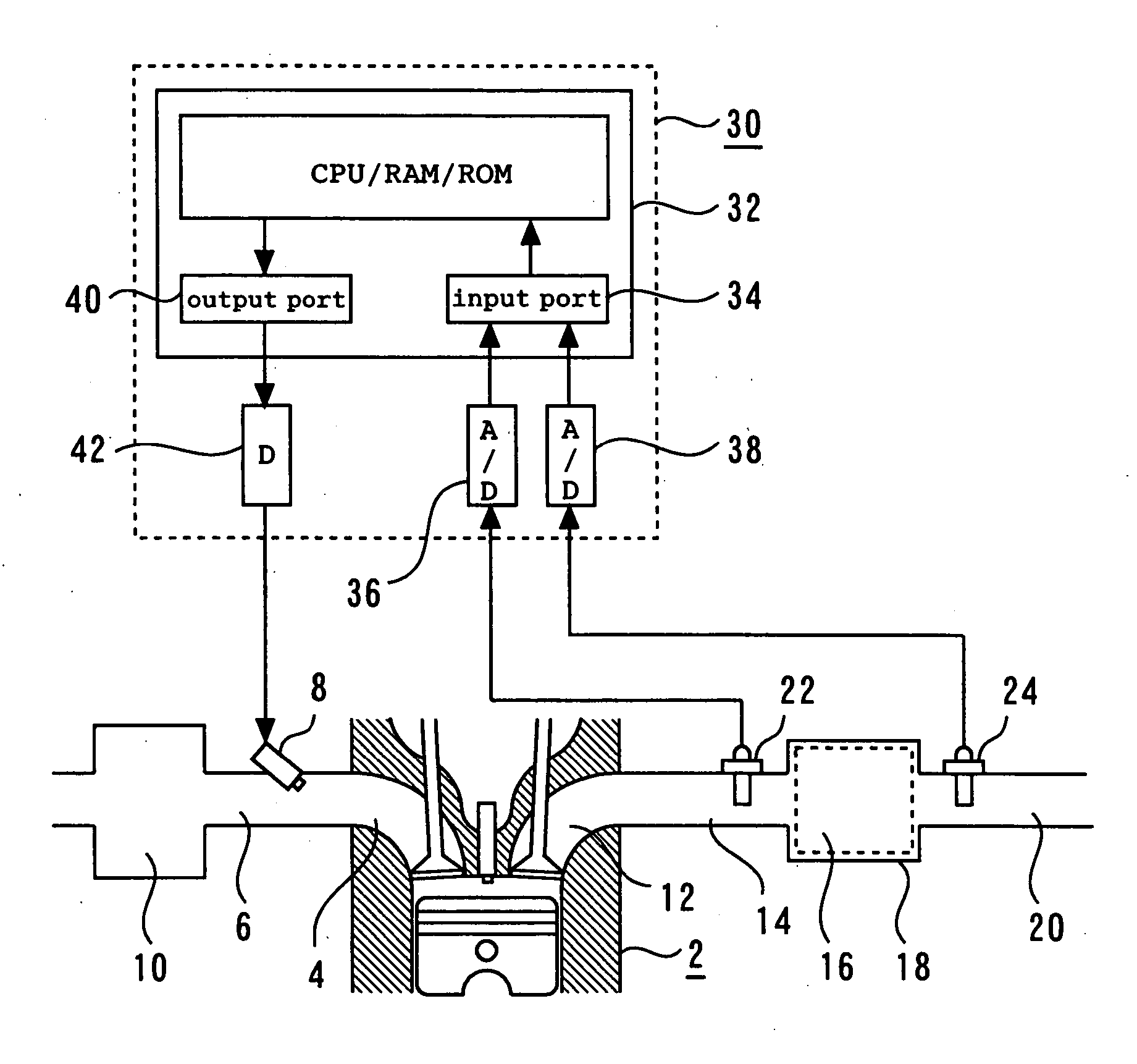
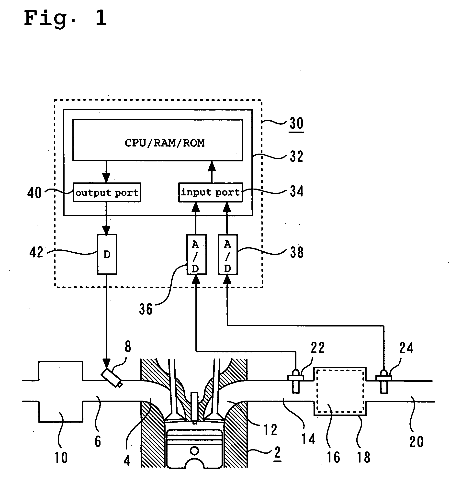
[0121]FIG. 1 is a schematic diagram illustrating a system according to a first embodiment of the present invention.

[0122] As shown in FIG. 1, the system according to the first embodiment includes an internal combustion engine 2. An intake branch pipe 6 is connected to an intake port 4 for each cylinder in the internal combustion engine 2. The intake branch pipe 6 includes a fuel injection valve 8. The intake branch pipe 6 is also connected to a common surge tank 10.

[0123] An exhaust port 12 for each cylinder in the internal combustion engine 2 is connected to a common exhaust manifold 14. The exhaust manifold 14 is connected to a catalytic converter 18 that incorporates a three-way catalyst 16. The catalytic converter 18 is connected to a muffler (not shown) via an exhaust pipe 20. An upstream sensor 22 is positioned upstream of the exhaust manifold 14, that is, upstream of the three-way catalyst 16. The upstream sensor 22 is a so-called wide-region air-fuel ratio sensor, which ge...

second embodiment

[0149] The system used in the second embodiment is configured the same as the system described in conjunction with the first embodiment. However, the control apparatus 30 stores two target voltages Vref1, Vref2 as the target voltages for calculating a deviation in accordance with the output V24 of the downstream sensor 24. FIG. 4 is a graph illustrating the relationship between the output of the downstream sensor 24 in the second embodiment and the two target voltages Vref1, Vref2.

[0150] As shown in FIG. 4, hysteresis occurs in the output characteristic of the downstream sensor 24 when the air-fuel ratio changes between rich and lean states in a low-concentration gas atmosphere. In other words, the output generated by the downstream sensor 24 when the air-fuel ratio changes from rich to lean differs from the output generated by the downstream sensor 24 when the air-fuel ratio changes from lean to rich. More specifically, when the air-fuel ratio changes from rich to lean, the sudden...


PUM

PropertyMeasurementUnit
porosityaaaaaaaaaa
thicknessaaaaaaaaaa
porosityaaaaaaaaaa

Abstract

An oxygen sensor generating an accurate output concerning low-concentration exhaust gas positioned downstream of a three-way catalyst. The oxygen sensor includes an exhaust gas side electrode exposed to an exhaust gas; a reference gas side electrode exposed to a reference gas serving as a reference for oxygen concentration; and an electrolyte positioned between the exhaust gas side electrode and the reference gas side electrode. Further, a reduction mechanism positioned toward a front surface of the exhaust gas side electrode ensures the ratio of the amount of exhaust gas introduced to the exhaust gas side electrode to the amount of an exhaust gas flow to the outside of the oxygen sensor is smaller than the ratio of the amount of exhaust gas introduced to an electrode for the air-fuel ratio sensor to the amount of an exhaust gas flow to the outside of the air-fuel ratio sensor.

Description

TECHNICAL FIELD [0001] The present invention relates to an oxygen sensor and air-fuel ratio control system, and more particularly to an oxygen sensor that is positioned downstream of a catalyst for an internal combustion engine and to an air-fuel ratio control system that includes sensors upstream and downstream of the catalyst for the internal combustion engine and exercises air-fuel ratio control by correcting the output of an air-fuel ratio sensor on the upstream side in accordance with the output of the oxygen sensor on the downstream side. BACKGROUND ART [0002] A system in which an air-fuel ratio sensor is positioned upstream of a three-way catalyst in an exhaust path for an internal combustion engine is disclosed by Japanese Patent Laid-Open No. 306742 / 1998. This system calculates an air-fuel ratio control parameter from the output of the air-fuel ratio sensor and uses the calculated parameter to adjust the air-fuel ratio for a target air-fuel ratio. [0003] The output of the a...

Claims


Application Information

Patent Timeline
Patent Type & Authority Applications(United States)
IPC IPC(8): G01N27/407
CPCG01N27/4077F02D41/1454
Inventor AOKI, KEIICHIRO
Owner TOYOTA JIDOSHA KK
Why Eureka
Try Eureka