Twin-vortex micromixer for enforced mass exchange

a micromixer and micro-vortex technology, applied in the field of passive micromixers, can solve the problems of difficult control of concentration gradients, no more work in microscopic laminar flow systems, and challenges for micromixers to fa

Inactive Publication Date: 2007-11-15
NATIONAL TSING HUA UNIVERSITY
View PDF10 Cites 33 Cited by
  • Summary
  • Abstract
  • Description
  • Claims
  • Application Information

AI Technical Summary

Benefits of technology

[0009] The primary objective of the present invention is to provide a micromixer, which can uniformly mix at least two fluids within a very short distance, such as few millimeters. The microchannel of the micromixer of the present invention is made of silicon, glass, or polymer. The microchannel of the present invention is formed and packaged via m...

Problems solved by technology

In a macroscopic flow field, a turbulent flow is usually used to implement mixing; however, it no more works in a microscopic laminar-flow system.
Such a problem is one of the challenges micromixers hav...

Method used


Image

  • Twin-vortex micromixer for enforced mass exchange
  • Twin-vortex micromixer for enforced mass exchange
  • Twin-vortex micromixer for enforced mass exchange

Examples


Embodiment Construction

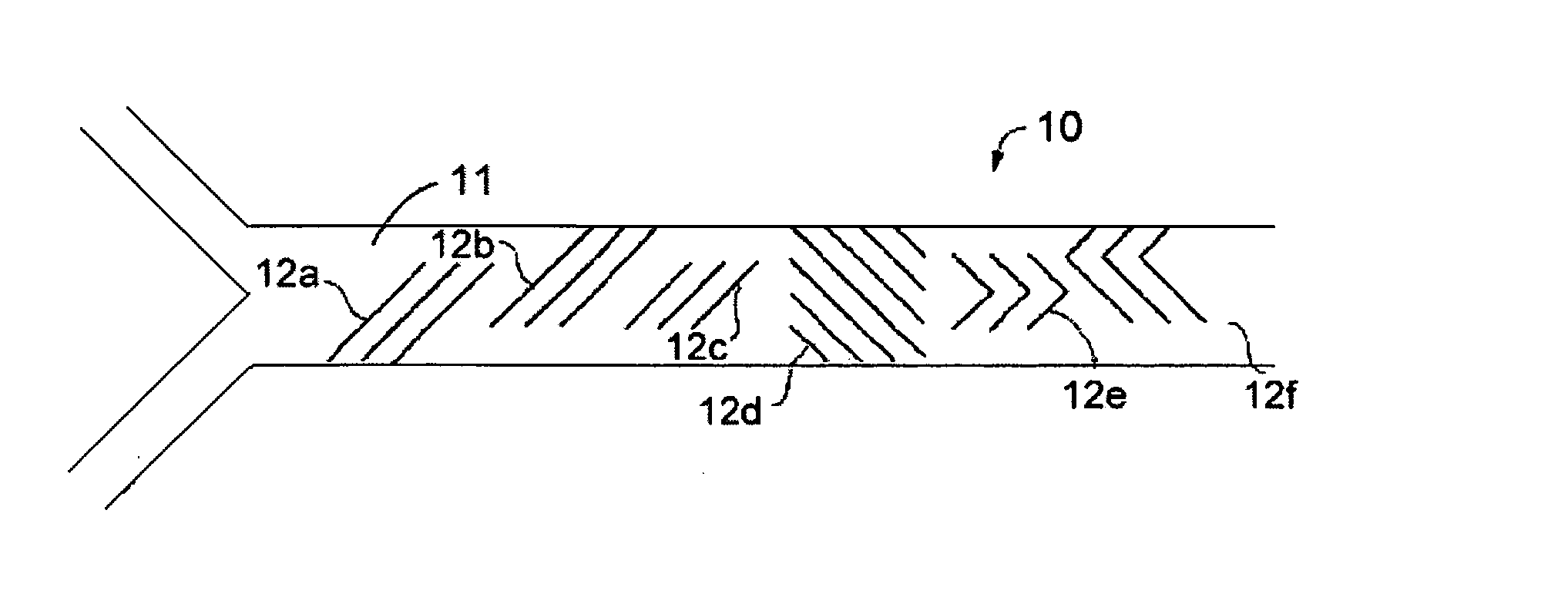
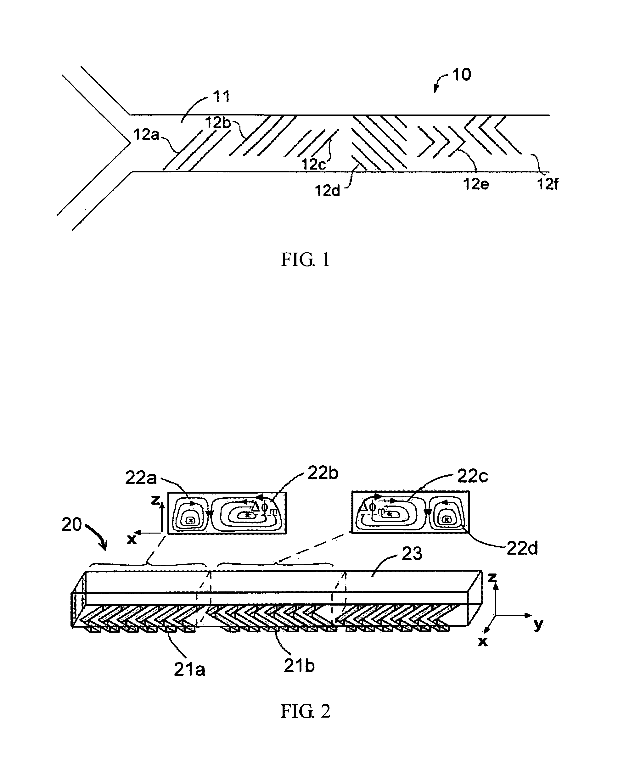
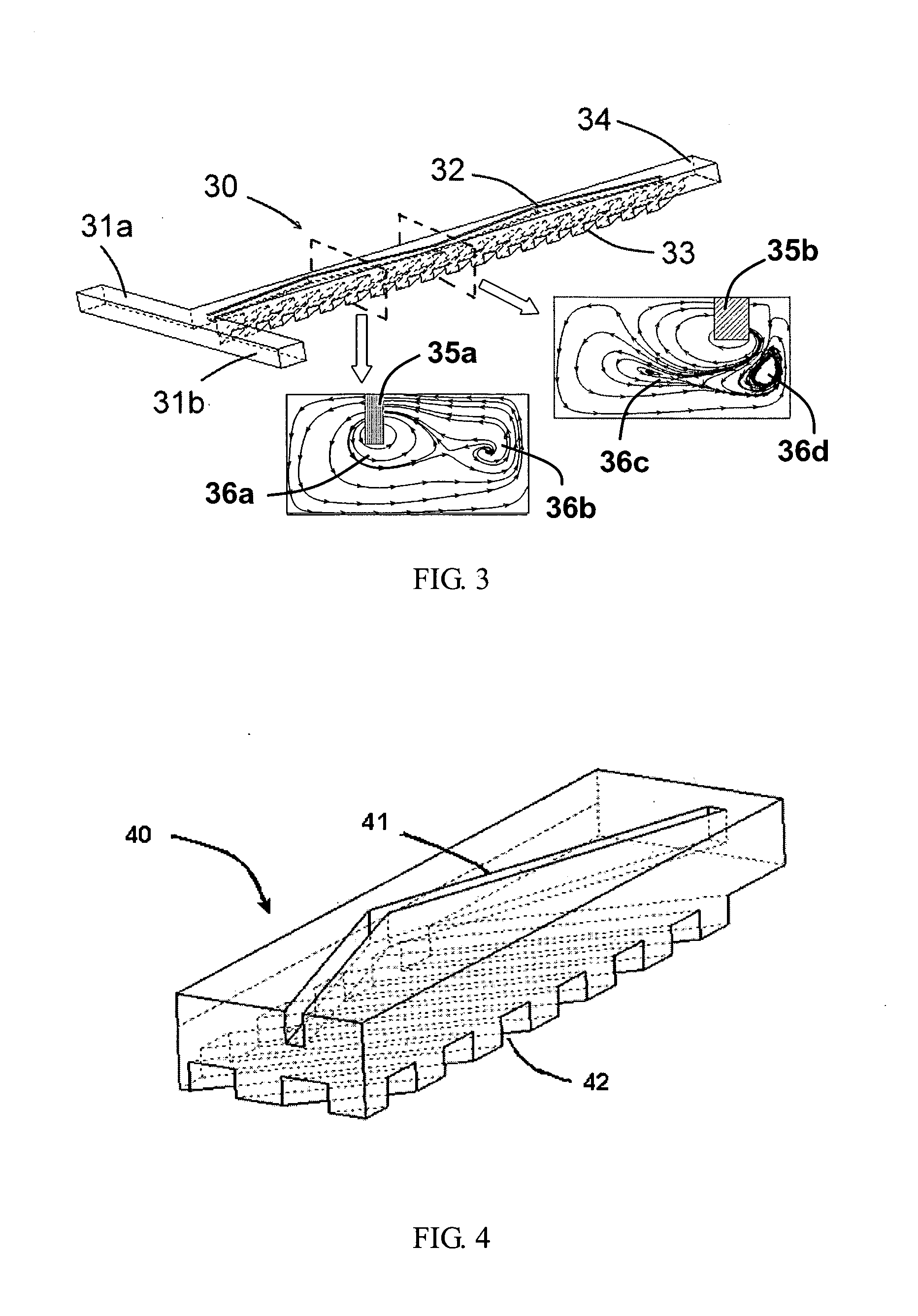
[0022] The present invention proposes a micromixer for enforced mass exchange. Refer to FIG. 3 a diagram schematically showing a preferred embodiment of the present invention. The mass-exchange-enforcing micromixer 30 comprises: a left inlet 31a, a right inlet 31b, a mixing chamber 37, and an outlet 34. At least two fluids enter into the mixing chamber 37 of the micromixer 30 via the left inlet 31a and the right inlet 31b respectively. The fluids are uniformly mixed in the mixing chamber 37, and then, the uniformly mixed fluids leave the micromixer 30 via the outlet 34. On at least one wall of the mixing chamber 37, such as the bottom wall, a lithographic process is exerted to form the grooves 33, which are sunk in the wall by at least tens to hundreds of microns and inclined to the main flow direction by some degrees. The grooves 33 may be simple slanted trenches or lying-V-shape trenches on the surface of the bottom wall. When the fluids flow through the grooves 33, the transverse...


PUM


Abstract

The present invention discloses a vortex-modulation based micromixer for enforced mass exchange. The micromixer of the present invention comprises a mixing chamber with grooves on one wall thereof and a special-shape barrier on another wall. As different fluids are injected into the mixing chamber respectively from two inlets of the micromixer, the grooves and barriers of the micromixer of the present invention create the constructive interferences to form the active-like agitation of the fluid. For every groove, the flux passed by can be increased via its high pressure gradient. Understandably, the mixing efficiency of the fluids can be greatly improved within a very short distance. At last, the outlet of the micromixer is located in the downstream of the mixing chamber and further is able to connect with other elements. The present invention is entirely a passive micromixer and no additional energy is required. The present invention can apply to a continuous chemical analysis, particularly to a lab-on-a-chip or a micro total analysis system.

Description

BACKGROUND OF THE INVENTION [0001] 1. Field of the Invention [0002] The present invention relates to a passive micromixer, which can uniformly mix at least two fluids within a very short distance. [0003] 2. Description of the Related Art [0004] Before, mixing was usually applied to the fields of mechanics and chemistry, such as chemical synthesis and combustion engineering. Because the advance in microelectromechanics brings rapid developments of microfluidics, a revolutionary development of biomedical chemistry is further inspired. Dismissing the original complicated biomedical analysis processes, procedures of standardized analysis are integrated onto a lab-on-a-chip or the micro total analysis system. A system integrating with microelectromechanics, biomedical technology, analytical chemistry, and optoelectronics is able to perform a series of test procedures of mixing, separation, and transportation, and has the advantages of small volume, low cost, parallel-processing capabilit...

Claims


Application Information

Patent Timeline
IPC IPC(8): B01F5/06B81B1/00
CPCB01F5/061B01F2005/0636B01F2005/0621B01F13/0059Y10S366/03B01F25/431B01F25/4317B01F25/431971B01F33/30
Inventor YANG, JING-TANGTUNG, KAI-YANGFANG, WEI-FENGHUANG, KER-JER
Owner NATIONAL TSING HUA UNIVERSITY
Why Eureka
Try Eureka