System Comprising a Low Phase Noise Waveguide Laser, a Method of Its Manufacturing and Its Use

a waveguide laser and low phase noise technology, applied in the field of lasers, can solve the problems of reducing affecting the efficiency of laser systems, so as to reduce the influence of vibrational pick up of laser systems and low phase noise

Inactive Publication Date: 2007-11-15
KOHERAS
View PDF19 Cites 26 Cited by
  • Summary
  • Abstract
  • Description
  • Claims
  • Application Information

AI Technical Summary

Benefits of technology

[0075] In a particular embodiment, the method further comprises the step of locating a feedback grating close to the output facet of the pump diode laser, close being defined as less than 1 m, such as less than 0.5 m, such as less than 0.2 m, such as less than 0.1 m, such as less than 0.05 m, such as less than such 0.01 m, thereby reducing the influence of vibrational pick up of the laser system.
[0076] Use of a system according to the invention as described above or in the accompanying claims or a system obtainable by the method according to the invention as described above or in the accompanying claims is moreover provided by the present invention. This has the advantage of enabling applications wherein a low phase noise laser system is required.

Problems solved by technology

Even though the total output intensity of the laser is stable, the chaotic mode behaviour, due to mode competition, induces amplitude noise of both the individual solitary laser chip and external cavity modes.
This noise induces absorption fluctuations.
Distortions will therefore modulate the refractive index and result in frequency jitter of the fibre laser.
The problem now is both mode-competition noise and the number of solitary cavity modes, covering the steep slope of the ytterbium absorption band.
Secondly the phonon-relaxation of the Erbium ions causes a temperature increase.
These index changes induce frequency jitter and an increased phase noise limited linewidth.

Method used


Image

  • System Comprising a Low Phase Noise Waveguide Laser, a Method of Its Manufacturing and Its Use
  • System Comprising a Low Phase Noise Waveguide Laser, a Method of Its Manufacturing and Its Use
  • System Comprising a Low Phase Noise Waveguide Laser, a Method of Its Manufacturing and Its Use

Examples


example 1

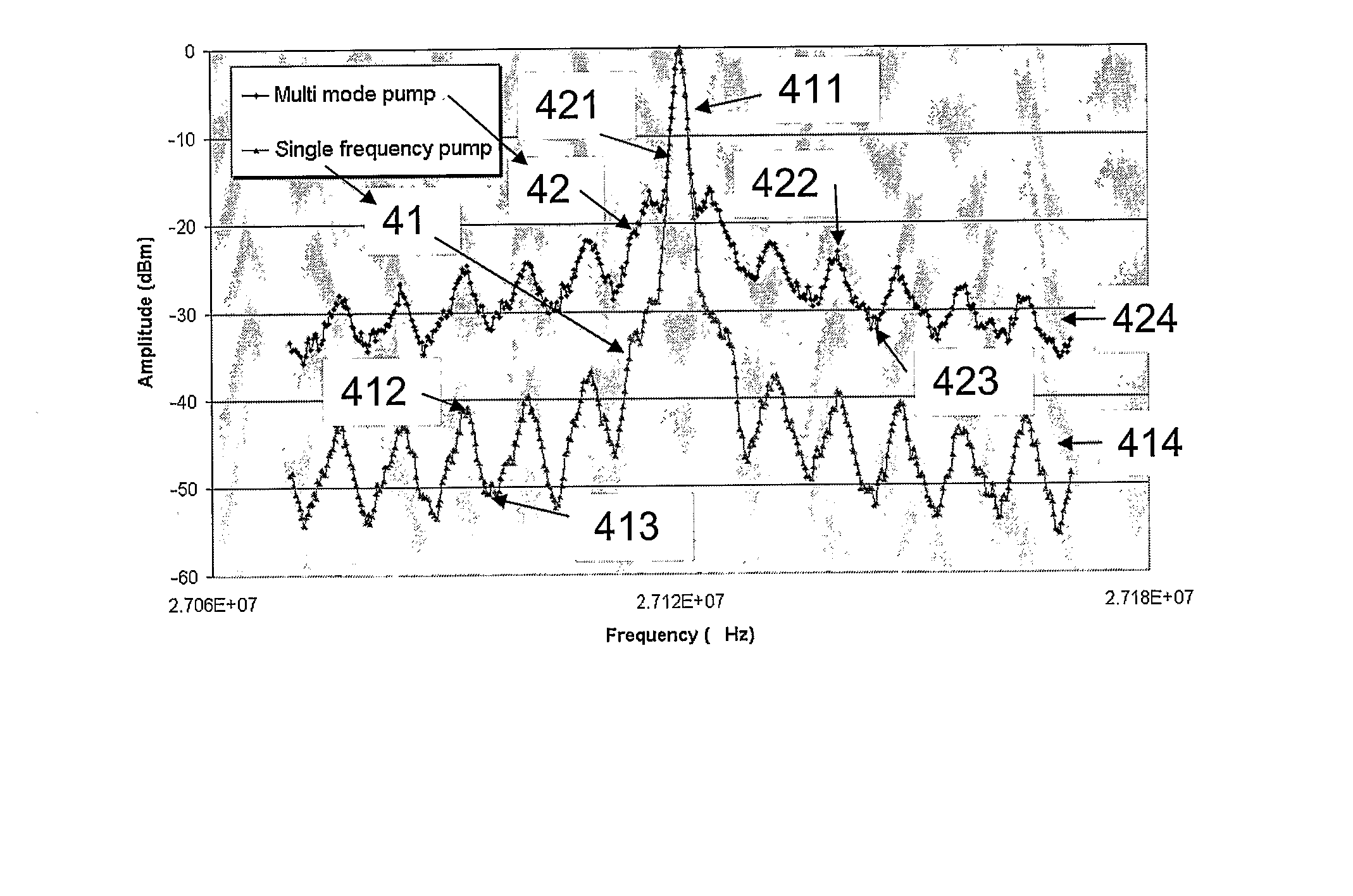
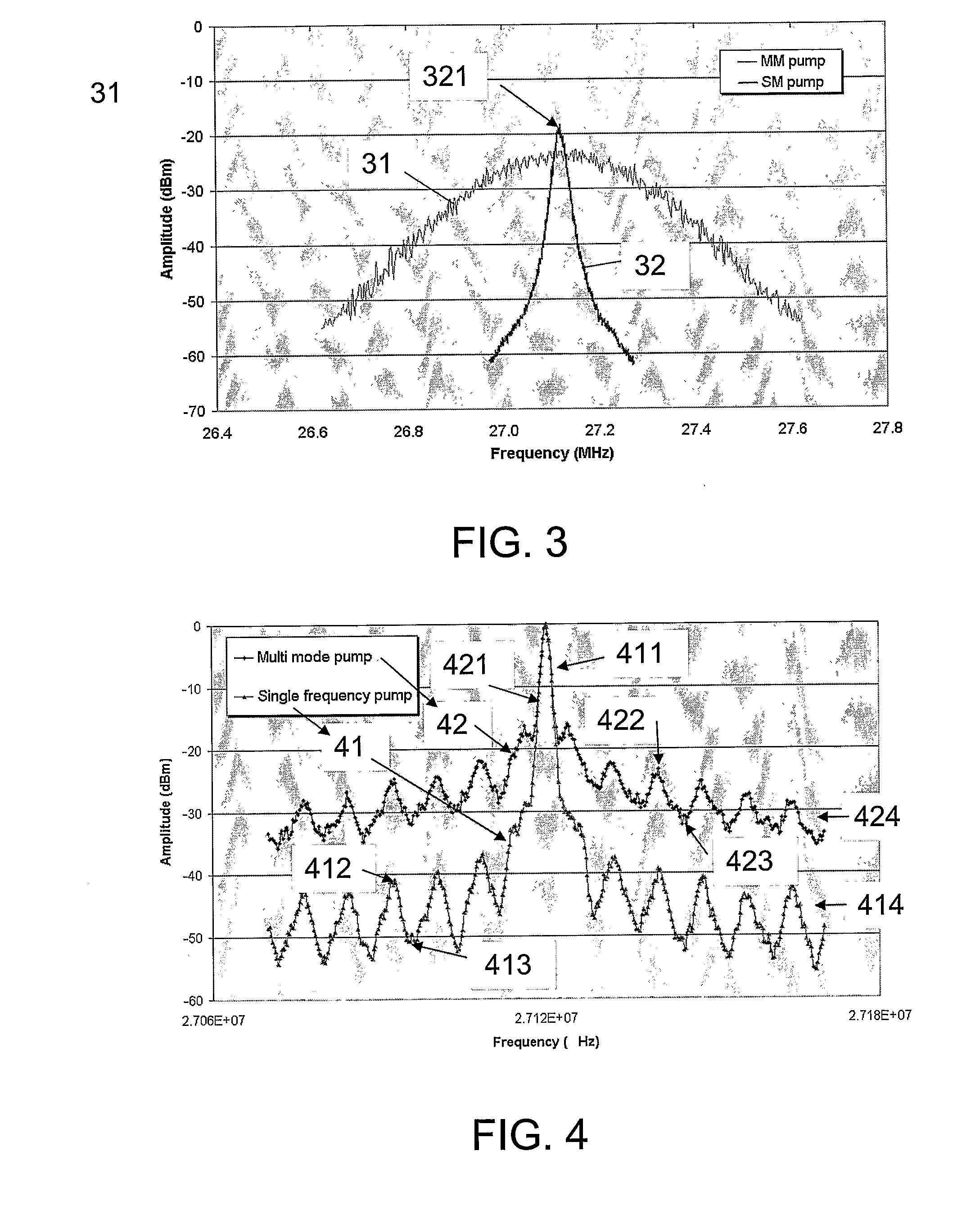
[0118]FIG. 11 shows the 20 dB full width of the beat signal (as described in FIG. 3 and FIG. 4) as a function of the fibre length between the pump laser diode and the fiber laser for a laser system according to the invention at a pump power of 200 mW. It follows from these measurements that the line width increases rapidly at relatively smaller fibre lengths (e.g. <2 m) and increases more gradually at relatively larger fibre lengths (e.g. approximately linearly above 6 m).

[0119] The measured behaviour could be explained by the pick up of acoustic or mechanical vibrations by the optical fiber (see e.g. “Fiber distributed feedback lasers used as acoustic sensors in air”, S. W. Løvseth et al., Applied Optics, Vol. 38, No. 22, 1999, p. 4821). The relationship between the frequency νa and the wavelength λa of these vibrations can be expressed by the simple formula: νa=cs / λa with cs the speed of light in the optical waveguide medium, here a silica fibre (approximately 6000 m / s). This is ...


PUM


Abstract

The invention relates to a system comprising a waveguide laser for exciting laser light at a lasing wavelength λs and a pump for pumping the waveguide laser at a pumping wavelength λp. The invention further relates to a method of providing such a system and its use. The object of the present invention is to provide a system comprising a waveguide laser with a reduced phase noise. The problem is solved in that the pump is a single frequency laser. The invention may e.g. be used in systems where an ultra-low phase noise and/or linewidth is required, e.g. in LIDAR or interferometric systems.

Description

TECHNICAL FIELD [0001] The invention relates generally to lasers and more particularly to waveguide lasers, e.g. Bragg grating based optical waveguide lasers with reduced phase noise characteristics. [0002] The invention relates specifically to a system comprising a waveguide laser for exciting laser light at a lasing wavelength λs and a pump for pumping the waveguide laser at a pumping wavelength λp. [0003] The invention furthermore relates to a method of providing a system for exciting laser light at a lasing wavelength λs. [0004] The invention furthermore relates to: Use of a system according to the invention or a system obtainable by the method according to the invention. [0005] The invention may e.g. be useful in applications where low phase noise and / or an ultra-low linewidth is required, e.g. in LIDAR or interferometric systems. BACKGROUND ART [0006] The following account of the prior art relates to one of the areas of application of the present invention, optical fibre laser...

Claims


Application Information

Patent Timeline
Patent Type & Authority Applications(United States)
IPC IPC(8): H01S3/0941H01S3/063H01S5/14H01S3/094
CPCH01S3/063H01S3/0675H01S5/146H01S3/094065H01S3/09415H01S3/08009
Inventor BEUKEMA, MARTIJNPOULSEN, CHRISTIAN VESTERGAARDPEDERSEN, JENS ENGHOLMVARMING, POUL
Owner KOHERAS
Why Eureka
Try Eureka