

Double-decker mask-pellicle assembly
a double-decker, mask-pellicle technology, applied in the field of pellicles, can solve the problems of destroying the circuit pattern, affecting the performance of the mask, so as to improve the strength and distortion resistance, prevent the leakage of atmospheric air, and improve the effect of pellicle strength
- Summary
- Abstract
- Description
- Claims
- Application Information
AI Technical Summary
Benefits of technology
Problems solved by technology
Method used
Image

Examples
first embodiment
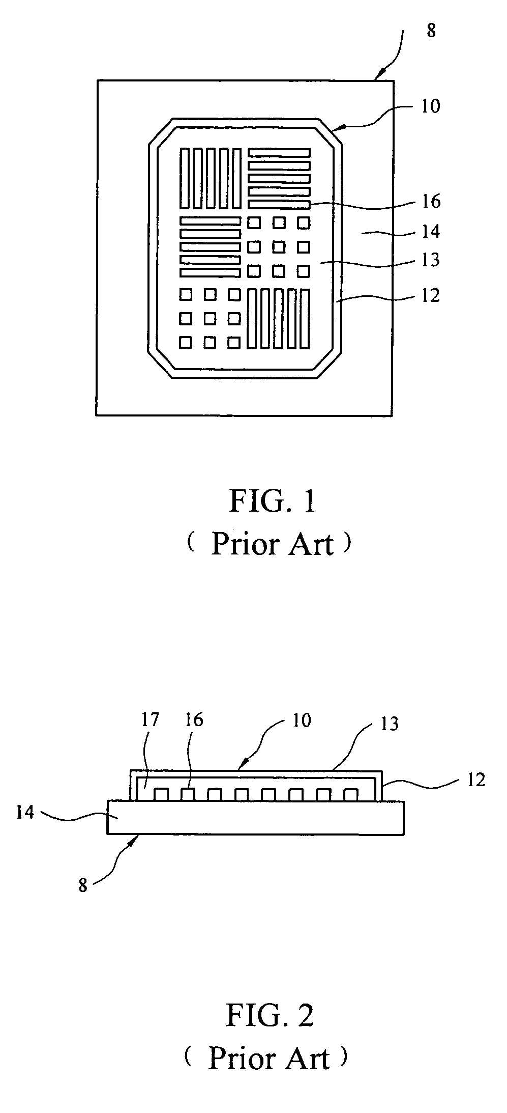
[0031] Referring initially to FIGS. 5 and 6, a pellicle-mask assembly of the present invention is generally indicated by reference numeral 29. The pellicle-mask assembly 29 includes a mask 30 having a transparent substrate 31 which may be quartz, for example. An absorber pattern and / or phase-shift pattern 32 is formed on the surface of the substrate 31 using techniques known by those skilled in the art. In fabrication of the pellicle-mask assembly 29, a hard pellicle 34, having a transparent pellicle body 35 which is typically quartz, is secured against the absorber pattern 32 using vacuum pressure. Preferably, the hard pellicle 34 has a thickness of at least about 1 mm. Accordingly, attachment of the hard pellicle 34 to the mask 30 may be carried out in a conventional vacuum chamber (not shown). In the fabricated pellicle-mask assembly 29, vacuum spaces 33 exist in the interstices defined by the absorber pattern 32, whereas air spaces 36 are defined between the substrate 31 and the...
second embodiment
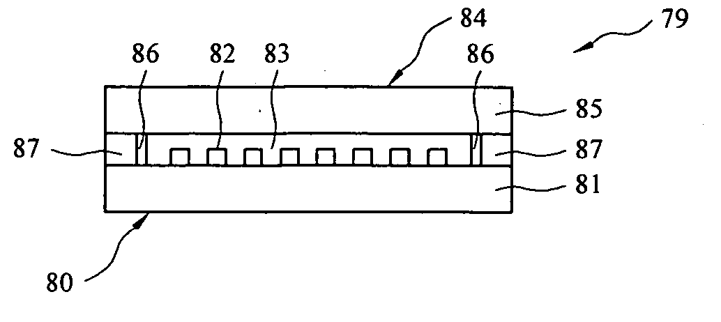
[0033] Referring next to FIGS. 7-10, a pellicle-mask assembly of the present invention is generally indicated by reference numeral 39 and includes a mask 40 having a transparent substrate 41 and an absorber pattern and / or phase-shift pattern 42 on the surface of the substrate 41. In fabrication of the pellicle mask assembly 39, a hard pellicle44, having a transparent pellicle body 45, is secured against the absorber pattern 42 using vacuum pressure, and this step may be carried out in a conventional vacuum chamber (not shown). In the fabricated pellicle-mask assembly 39, vacuum spaces 43 exist in the interstices defined by the absorber pattern 42. A soft sealing frame 46, which may be plastic, for example, is interposed between the mask substrate 41 and the pellicle body 45 along the edges or perimeter of the absorber pattern 42. In the embodiment of the pellicle-mask assembly 39a shown in FIGS. 9 and 10, the sealing frame 46a is rubber. An alternative material for the sealing frame...
third embodiment
[0034] Referring next to FIG. 11, a pellicle-mask assembly of the present invention is generally indicated by reference numeral 59 and includes a mask 60 having a transparent substrate 61 and an absorber pattern and / or phase shift pattern 62 on the surface of the substrate 61. A hard pellicle 64, having a transparent pellicle body 65, is secured against the absorber pattern 62 using vacuum pressure. Vacuum spaces 63 exist in the interstices defined by the absorber pattern 62 and at the edges or perimeter of the absorber pattern 62. A flat O-ring 66, which may be rubber or plastic, for example, is provided along the edges of the pellicle-mask assembly 59, and tightly engages the edges of the mask substrate 61 and pellicle body 65. The vacuum pressure in the vacuum spaces 63 secures the pellicle 64 to the mask 60. The O-ring 66 prevents air from entering between the mask substrate 61 and pellicle body 65, thus maintaining the integrity of the vacuum pressure in the vacuum spaces 63.
PUM
 Abstract
Description
Claims
Application Information