
Manufacturing method of tunnel magnetoresistive effect element, manufacturing method of thin-film magnetic head, and manufacturing method of magnetic memory

Inactive Publication Date: 2007-11-15
TDK CORPARATION
View PDF1 Cites 23 Cited by
  • Summary
  • Abstract
  • Description
  • Claims
  • Application Information

AI Technical Summary

Benefits of technology

[0011]It is therefore an object of the present invention to provide a manufacturing method of a TMR element, a manufacturing method of a thin-film magnetic head and a manufacturing method of a magnetic memory, whereby it is possible to stably obtain TMR elements having a high MR ratio.
[0013]When fabricating the tunnel barrier layer, the atmosphere with an impurity concentration of 1E-02 or less is provided, as the environment in which the deposited first metallic material film is oxidized, to keep high cleanliness. This allows obtaining a higher MR ratio stably even when there is used Mg as a barrier material more reactive on oxygen than Al conventionally used as the barrier material.
[0016]In this case, preferably, the flow oxidation is performed by flowing O2 gas only. Increment of the O2 gas flow rate allows improvement of cleanliness of the oxidation atmosphere.
[0017]In this case, also preferably, the flow oxidation is performed by flowing O2 gas and purification gas that does not contribute to the oxidation. By flowing the purification gas that does not contribute to oxidation with O2 gas by a large quantity, cleanliness of the oxidation atmosphere can be improved. In this case, more preferably, the purification gas may be at least one kind of rare gas nitrogen (N2) gas and hydrogen (H2) gas. The rare gas may include helium (He) gas, neon (Ne) gas, argon (Ar) gas, krypton (Kr) gas or xenon (Xe) gas.

Problems solved by technology

However, if the MgO target is used, it is unavoidable to have uneven resistance among substrates, caused by uneven resistance due to film-thickness distribution of an MgO film on a substrate and by fluctuation of film-deposition speed of the MgO film by the RF sputtering.
However, Mg is material more reactive on oxygen than Al that is generally used as material for the tunnel barrier layer, and therefore easily affected by cleanliness of an oxidation atmosphere, primarily by moisture impurity concentration.
As a result, it has been very difficult to stably obtain TMR elements having a high MR ratio.
However, an oxidation process with actual use of Mg is not disclosed at all.

Method used


Image

  • Manufacturing method of tunnel magnetoresistive effect element, manufacturing method of thin-film magnetic head, and manufacturing method of magnetic memory
  • Manufacturing method of tunnel magnetoresistive effect element, manufacturing method of thin-film magnetic head, and manufacturing method of magnetic memory
  • Manufacturing method of tunnel magnetoresistive effect element, manufacturing method of thin-film magnetic head, and manufacturing method of magnetic memory

Examples


Embodiment Construction

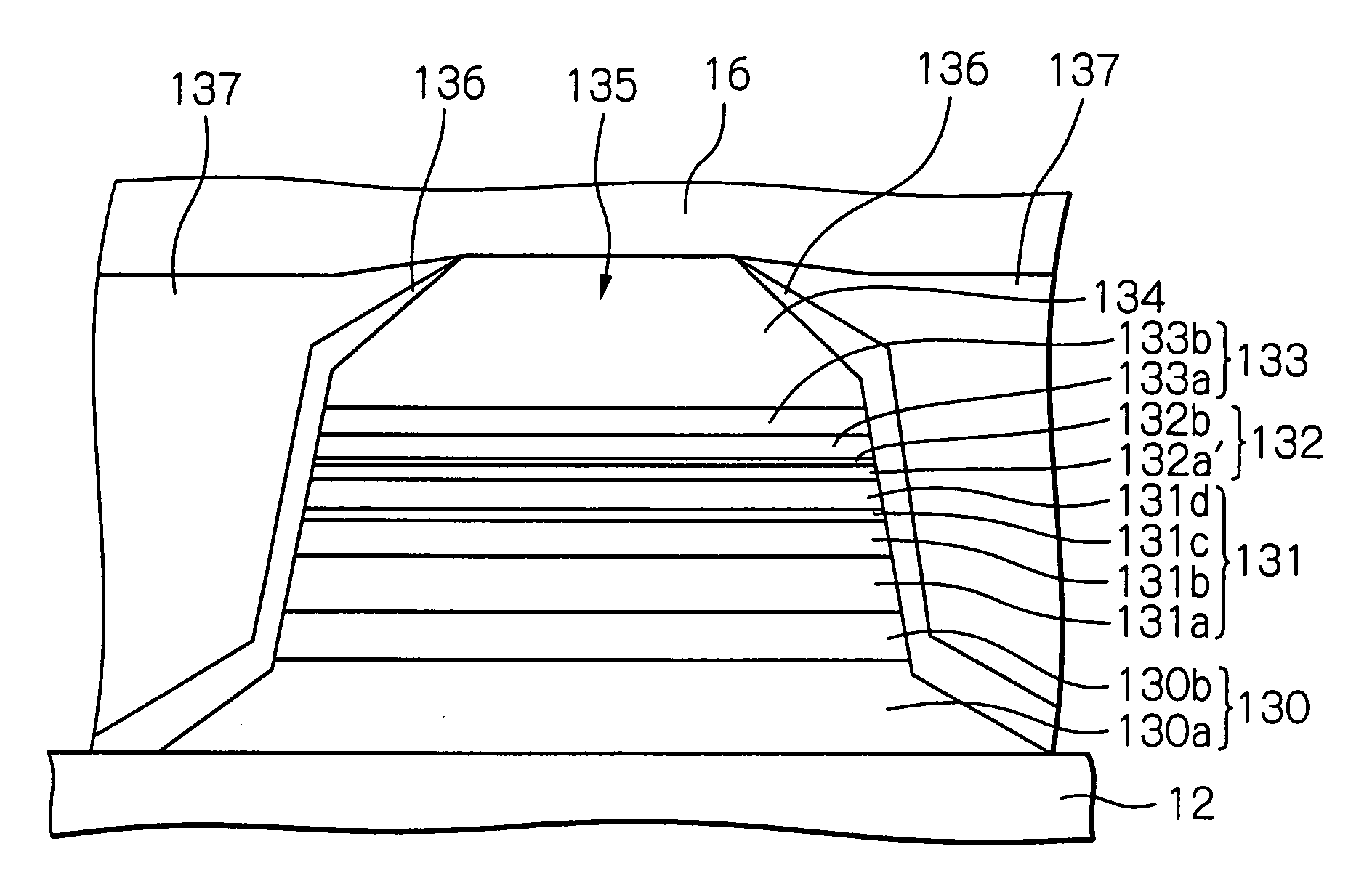
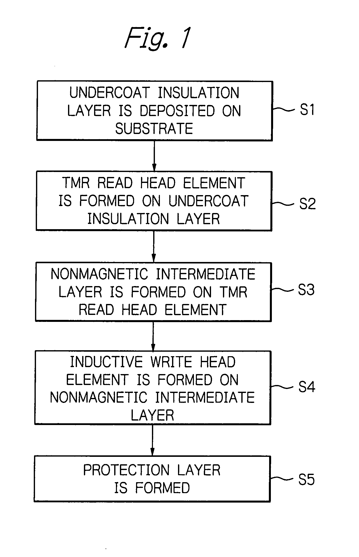
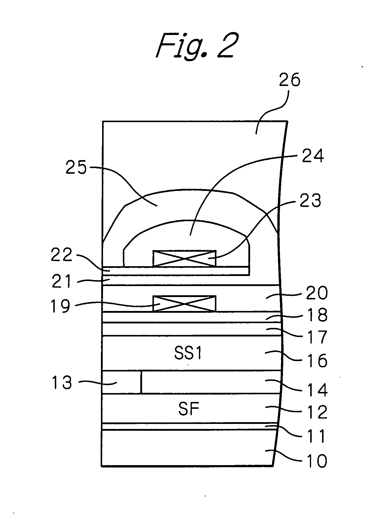
[0030]FIG. 1 illustrates a flow of a fabrication process of a thin-film magnetic head in a preferred embodiment according to the present invention, FIG. 2 schematically illustrates a structure of the thin-film magnetic head produced according to the fabrication process shown in FIG. 1, FIG. 3 illustrates in more detail a fabrication process of a read head element part in the fabrication process shown in FIG. 1, and FIG. 4 schematically illustrates a structure of the read head element part in the thin-film magnetic head shown in FIG. 2. It should be noted that FIG. 2 shows a cross section of the thin-film magnetic head on a plane perpendicular to an air bearing surface (ABS) and a track width direction, and FIG. 4 shows a cross section seen from the ABS direction.

[0031]As shown in FIGS. 1 and 2, a substrate or wafer 10 made of conductive material such as ALTIC (AlTiC, Al2O3—TiC) is first prepared. On the substrate 10, an undercoat insulation layer 11 is formed by deposition of insula...


PUM


Abstract

A manufacturing method of a TMR element having a magnetization fixed layer, a magnetization free layer and a tunnel barrier layer sandwiched between the magnetization fixed layer and the magnetization free layer. A fabricating process of the tunnel barrier layer includes a step of depositing a first metallic material film on the magnetization fixed layer or the magnetization free layer, and a step of oxidizing the deposited first metallic material film under an environment with an impurity concentration of 1E-02 or less.

Description

PRIORITY CLAIM[0001]This application claims priority from Japanese patent application No. 2006-132410, filed on May 11, 2006, which is incorporated herein by reference.BACKGROUND OF THE INVENTION[0002]1. Field of the Invention[0003]The present invention relates to a manufacturing method of a tunnel magnetoresistive effect (TMR) element, a manufacturing method of a thin-film magnetic head having a TMR element, and a manufacturing method of a magnetic memory.[0004]2. Description of the Related Art[0005]The TMR element has a ferromagnetic tunnel junction structure in which a tunnel barrier layer is sandwiched between two ferromagnetic layers, and an anti-ferromagnetic layer is arranged on a surface of one of the ferromagnetic layers, which surface is not contacting the tunnel barrier layer. Thus, one of these ferromagnetic layers functions as a magnetization fixed layer, in which the magnetization of this ferromagnetic layer is hard to move in response to an external magnetic field due...

Claims


Application Information

Patent Timeline
IPC IPC(8): H01L21/00
CPCB82Y25/00B82Y40/00G01R33/093G01R33/098H01L43/12G11B5/3906G11C11/16H01F10/3254H01F41/307G11B5/3163H10N50/01
Inventor MIURA, SATOSHIUESUGI, TAKUMI
Owner TDK CORPARATION
Learn More