Color sensor, production method thereof, sensor, and electronics device

a color sensor and color technology, applied in the field of color sensors, can solve the problems of interference with color analysis, inability of human eyes to see infrared light, and inability to detect infrared light, so as to prevent photoelectric current and achieve precise color analysis

Inactive Publication Date: 2007-11-22
SHARP KK
View PDF3 Cites 2 Cited by
  • Summary
  • Abstract
  • Description
  • Claims
  • Application Information

AI Technical Summary

Benefits of technology

[0021]An object of the present invention is to provide a color sensor, which is capable of (i) preventing a photoelectric current from being generated by near infrared light and infrared light and (ii) performing a precise color analysis, a production method of the color sensor, a sensor including the color sensor, and an electronics device including the color sensor.

Problems solved by technology

However, it is being examined due to improved luminous efficiency of an LED, an environmental problem, or the like, to change the mercury lamp to an LED light source.
Although a silicon photodiode is generally very sensitive to near infrared light having a wavelength in a range from 700 nm to 900 nm, eyes of a human being cannot see infrared light.
Accordingly, a photoelectric current generated by near infrared light becomes a noise component in color analysis and interferes with a precise color analysis.
This arrangement causes a problem such that the visible light transmitting filter 117 easily comes off the transparent resin 116 by mechanical or thermal stress.

Method used


Image

  • Color sensor, production method thereof, sensor, and electronics device
  • Color sensor, production method thereof, sensor, and electronics device
  • Color sensor, production method thereof, sensor, and electronics device

Examples


Embodiment Construction

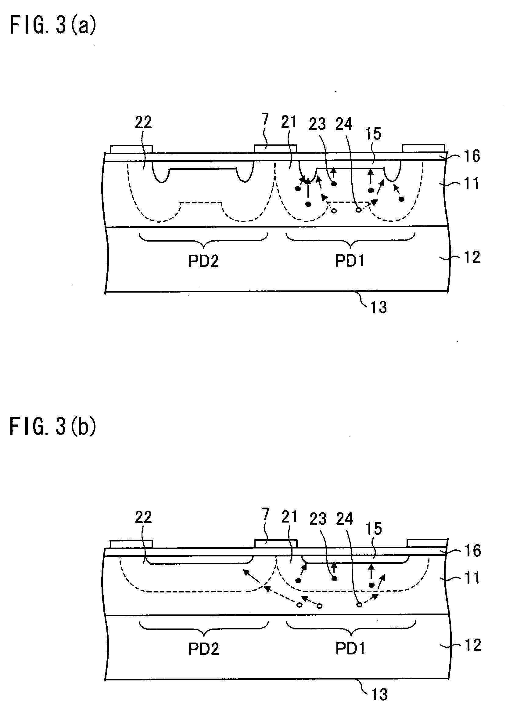
[0039]One embodiment of the present invention is explained below with reference to FIGS. 1 through 3.

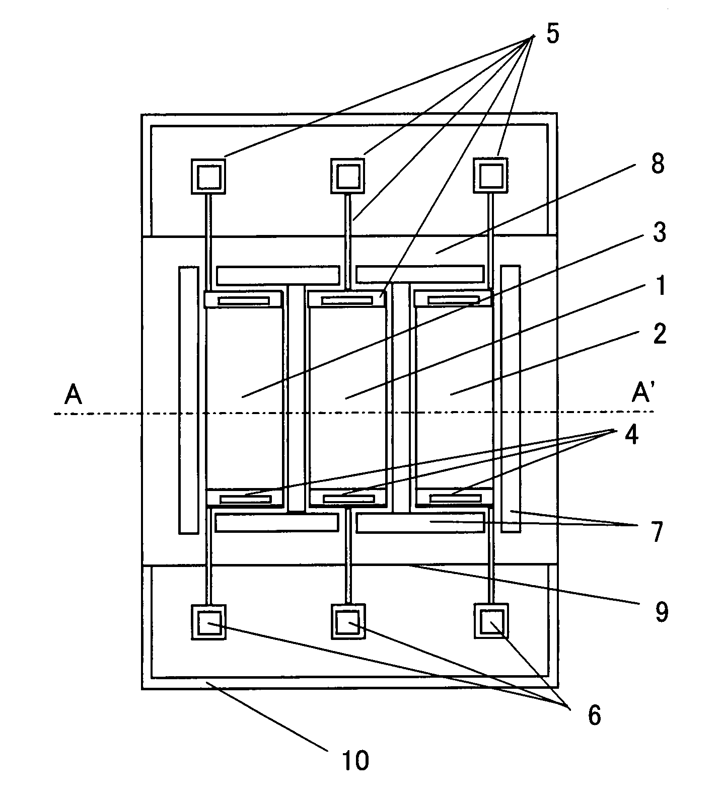
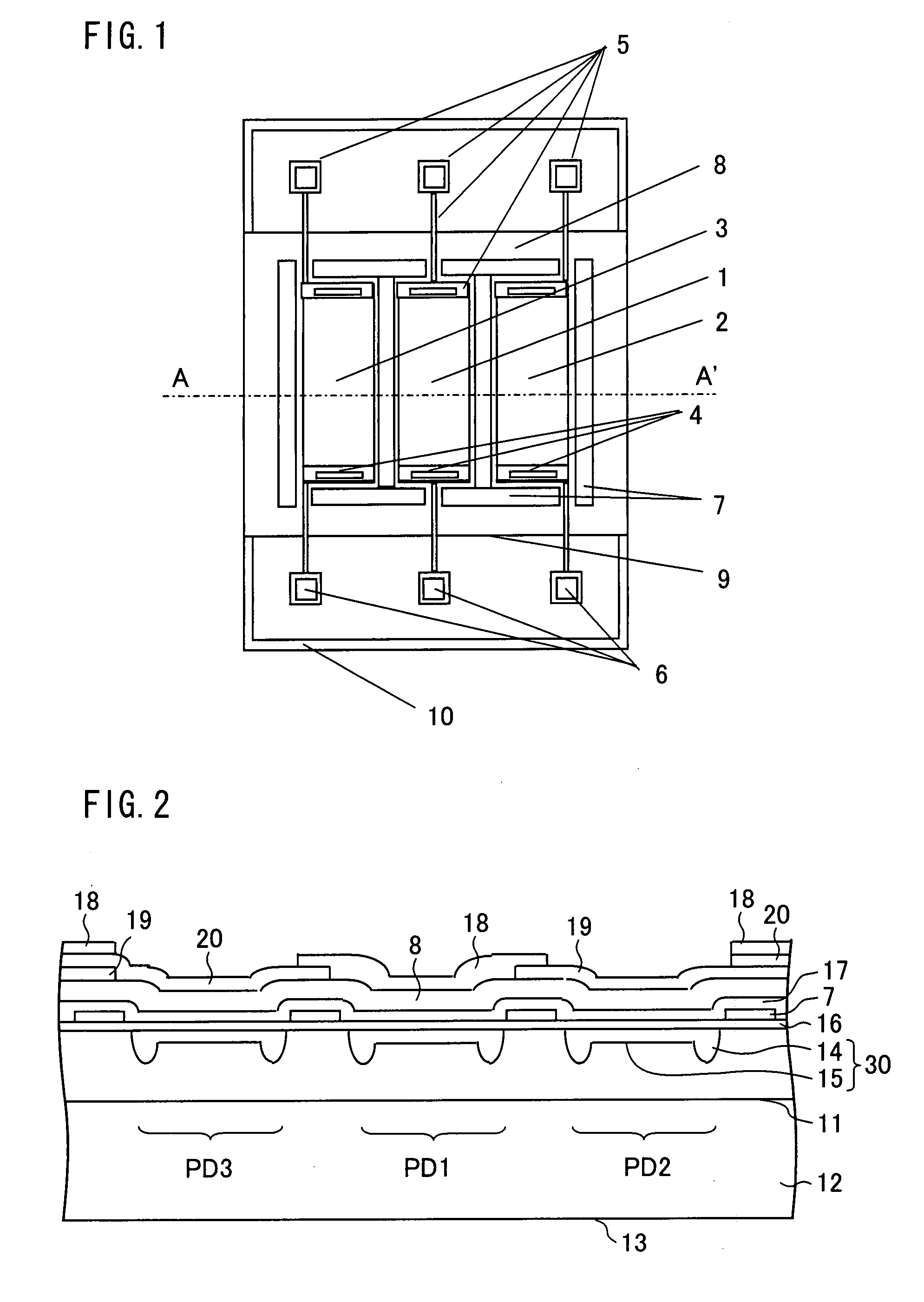
[0040]FIG. 1 is a plan view illustrating a color sensor of the present embodiment.

[0041]FIG. 2 is a cross sectional view taken along a line A-A′ of FIG. 1.

[0042]As illustrated in FIG. 2, the color sensor of the present embodiment includes a silicon epitaxial wafer in which an N− epitaxial layer 11 (serving as a first conductive layer) is formed, by using an epitaxial growth, on an N+ substrate 12 (serving as a first conductive semiconductor substrate). The N− epitaxial layer 11 of the silicon epitaxial wafer includes a P-type anode layer 30 (serving as a second conductive layer). The P-type anode layer 30 is composed of a frame-like periphery section 14 and a center region 15.

[0043]Moreover, the color sensor includes three photodiodes PD1, PD2, and PD3 which are formed to be light receiving elements by the P-type anode layer 30, the N+ substrate 12 (serving as a cathode shared by the...


PUM


Abstract

A color sensor of the present invention is arranged such that (i) an interference filter is provided directly above light receiving elements so as to transmit incoming light having a predetermined wavelength of the incoming light, and color filters are provided directly on the interference filter, or (ii) the color filters are provided directly above the light receiving element, and the interference filter is provided directly on the color filters so as to transmit incoming light having a predetermined wavelength of the incoming light.

Description

[0001]This Nonprovisional application claims priority under 35 U.S.C. §119(a) on Patent Application No. 140927 / 2006 filed in Japan on May 19, 2006, the entire contents of which are hereby incorporated by reference.FIELD OF THE INVENTION[0002]The present invention relates to a color sensor, which is used for, for example, (i) a backlight of a liquid crystal display, and (ii) an image scanning device that preforms (a) color adjustment of a color copying machine and a color printer, (b) discriminant analysis of paper money, or the like, a production method of the color snesor, a sensor including the color sensor, and an electronics device including the color sensor.BACKGROUND OF THE INVENTION[0003]Conventionally, a mercury lamp has been generally used as a backlight of a liquid crystal display. However, it is being examined due to improved luminous efficiency of an LED, an environmental problem, or the like, to change the mercury lamp to an LED light source. Particularly in a case of a...

Claims


Application Information

Patent Timeline
Patent Type & Authority Applications(United States)
IPC IPC(8): H04N9/04
CPCG02B5/201G02B5/28H01L27/14685H01L27/14623H01L27/14621
Inventor KOYAMA, JUNICHIRO
Owner SHARP KK
Why Eureka
Try Eureka