Fans and turbines

a technology of fan and turbine, which is applied in the direction of electrical-based machining apparatus, climate sustainability, air transportation, etc., can solve the problems of intractable construction of such bladed discs, excessively difficult pattern construction, and reduced precision, so as to promote the desired airflow, reduce stress concentration in the formed blades, and achieve high precision

Active Publication Date: 2007-11-29
BLADON JETAB HLDG
View PDF4 Cites 17 Cited by
  • Summary
  • Abstract
  • Description
  • Claims
  • Application Information

AI Technical Summary

Benefits of technology

[0031] At the simplest, the shape of the elongate electrode may be rectilinear, but this will not generate an aerofoil surface in a single pass. It is much preferred to curve the electrode, and a simple circular arc may suffice. The curve should be smooth. Sharp or abrupt changes in shape are generally to be avoided, to minimize stress concentrations in the formed blades, and to promote the desired airflow over them.
[0032] The dimensions of the electrode can be described as length, width and depth. Being elongate, the width and depth are small relative to the length, which extends across the thickness of the edge of the workpiece to form the groove. The width of the electrode corresponds to the width of the groove as it is being formed at any instant, less the proximity gaps between the electrode and each side of the groove where the erosion of the workpiece material is taking place. The depth of the e...

Problems solved by technology

In scaling down the size of such engines, engineering problems are met as dimensions decrease.
Some of these problems are to do with the difficulties of further miniaturisation at a manufacturing level, and some to do with the behaviours of gas flows in relatively small spaces.
In the case of a very small engine, a disc might be cast with integral blades, but there are serious problems due to the...

Method used


Image

  • Fans and turbines
  • Fans and turbines
  • Fans and turbines

Examples


Embodiment Construction

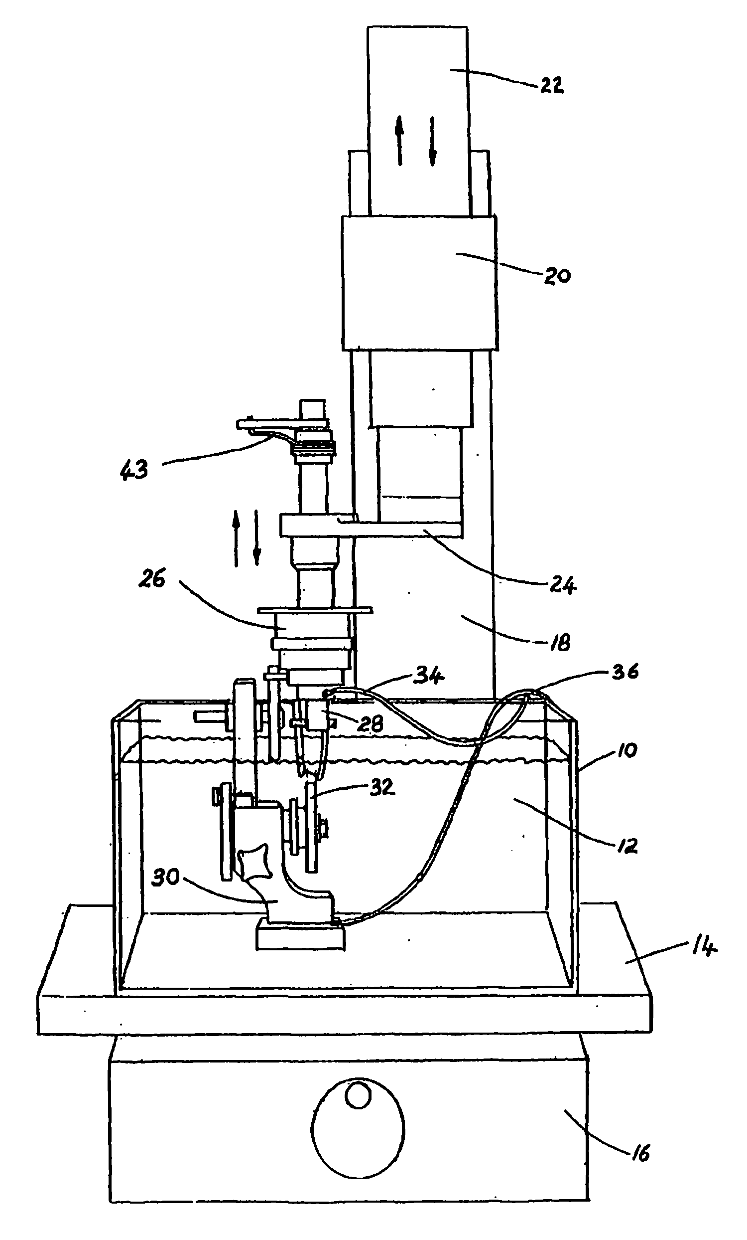
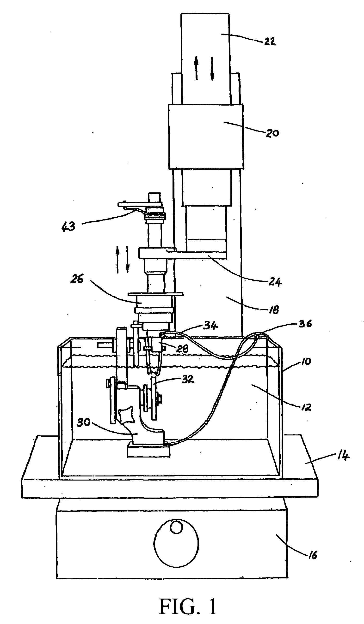
[0059] Referring first to FIG. 1, the illustrated apparatus comprises a tank 10 containing a suitable liquid quenching medium 12, which is a dielectric fluid such as a suitable paraffin oil or water based alternative, in which to conduct spark erosion operations. The tank is supported by a platform 14, under which is a housing 16 for the necessary electrical and control equipment, which is of any kind that is in itself known in the art.

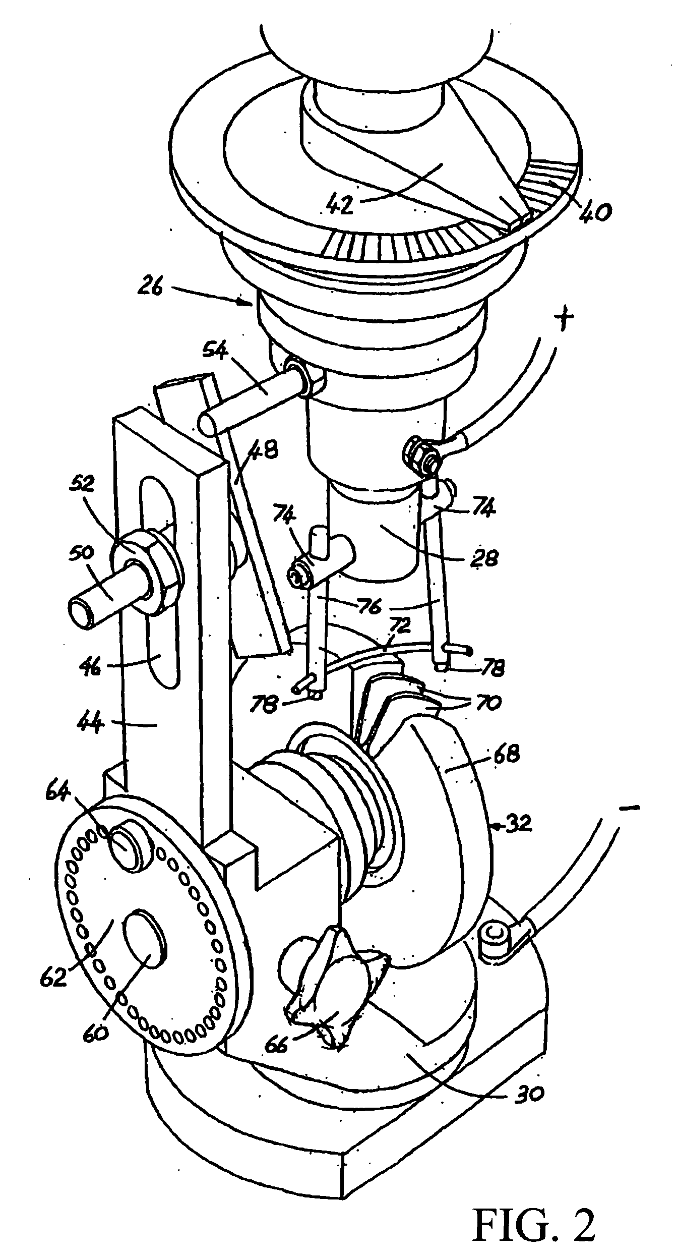
[0060] Behind tank 10, as shown, is a pillar 18. Towards its upper end the pillar carries a hydraulic drive 20, which moves a drive column 22 up and down under the control of the equipment in housing 16. An electronic servo drive may be an acceptable alternative. The lower end of the drive column carries a horizontal support arm 24, which carries tool holder head 26, to be described in more detail in relation to FIG. 2. The tool holder head carries tool holder 28.

[0061] Within tank 10, immersed in the liquid 12, is a pedestal 30, which carries a wor...


PUM

PropertyMeasurementUnit
Thicknessaaaaaaaaaa
Radiusaaaaaaaaaa

Abstract

Overlapping twisted radial aerofoil blades or vanes are formed on a compressor rotor or turbine disk or the like (102) by electro-discharge machining with a curved tool electrode which is in the form of an elongate and substantially rigid element other than a wire (150) which is turned by a tool holder (130) as it is advanced on a helical path to form the inner surface of each blade or vane with the outer curve of the electrode, or the outer surface of each blade or vane with the inner curve of the electrode, the disk being indexed to a next rotary position after each blade surface is machined.

Description

CROSS-REFERENCE TO RELATED APPLICATION(S) [0001] The present application is a continuation of International Application PCT / GB2005 / 03491, with an international filing date of 9 Sep. 2005, and is a continuation-in-part of co-pending U.S. application Ser. No. 10 / 546,884 filed on 26 Aug. 2005.BACKGROUND OF THE INVENTION [0002] (1) Field of the Invention [0003] The present invention relates to a process, method and apparatus, with particular reference to the manufacture of fans and turbines (for dynamic interaction with fluid flows) and guide vanes (for static interaction with fluid flows), especially for use in turbomolecular pumps and in gas turbine engines. [0004] (2) Description of Prior Art [0005] Gas turbine engines are a widely used form of internal combustion engine and are in many senses more efficient than reciprocating engines operating on the two- or four-stroke principle. In particular, for a given size, the gas turbine can give a higher power output. [0006] Much gas turbin...

Claims


Application Information

Patent Timeline
IPC IPC(8): B23P13/04B23H1/04B23H9/10
CPCB23H1/04B23H7/26B23H9/10Y10T29/49325F04D29/388Y02T50/671F05D2230/12F01D5/34Y02T50/60
Inventor BLADON, CHRISTOPHER GEORGEBLADON, PAUL DOUGLAS
Owner BLADON JETAB HLDG
Why Eureka
Try Eureka