
Environmental sensor

a sensor and environment technology, applied in the direction of liquid/fluent solid measurement, fluid speed measurement using thermal variables, indication/recording movement, etc., can solve the problems of inconvenient deployment and maintenance of sensors, inability to meet the needs of such applications, and inability to calibrate sensors discussed above. , to achieve the effect of being easy to deploy and maintain

Inactive Publication Date: 2007-11-29
M B T L
View PDF9 Cites 156 Cited by
  • Summary
  • Abstract
  • Description
  • Claims
  • Application Information

AI Technical Summary

Benefits of technology

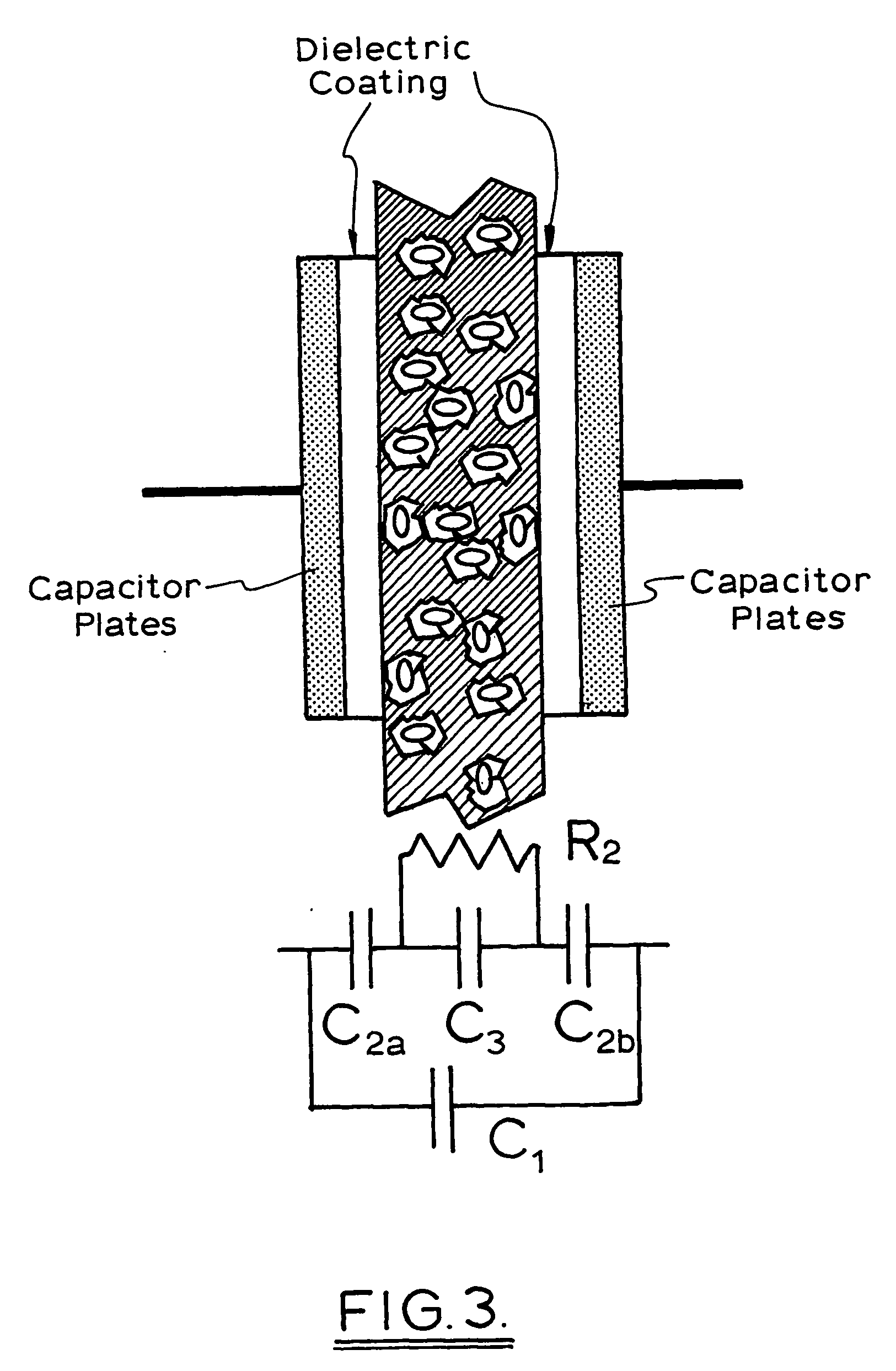
[0021] In another aspect of this invention there is provided a capacitive sensor which may be used for measuring soil moisture or leaf wetness, which includes at least one pair of sensor pads one of each pair consisting of a conductor covered by a dielectric layer and the other of each pair consisting of a conductor covered by the same dielectric layer with a top conducting layer. This arrangement has the advantage of providing the second sensor pad as a reference capacitor so that manual calibration of the sensor is unnecessary.
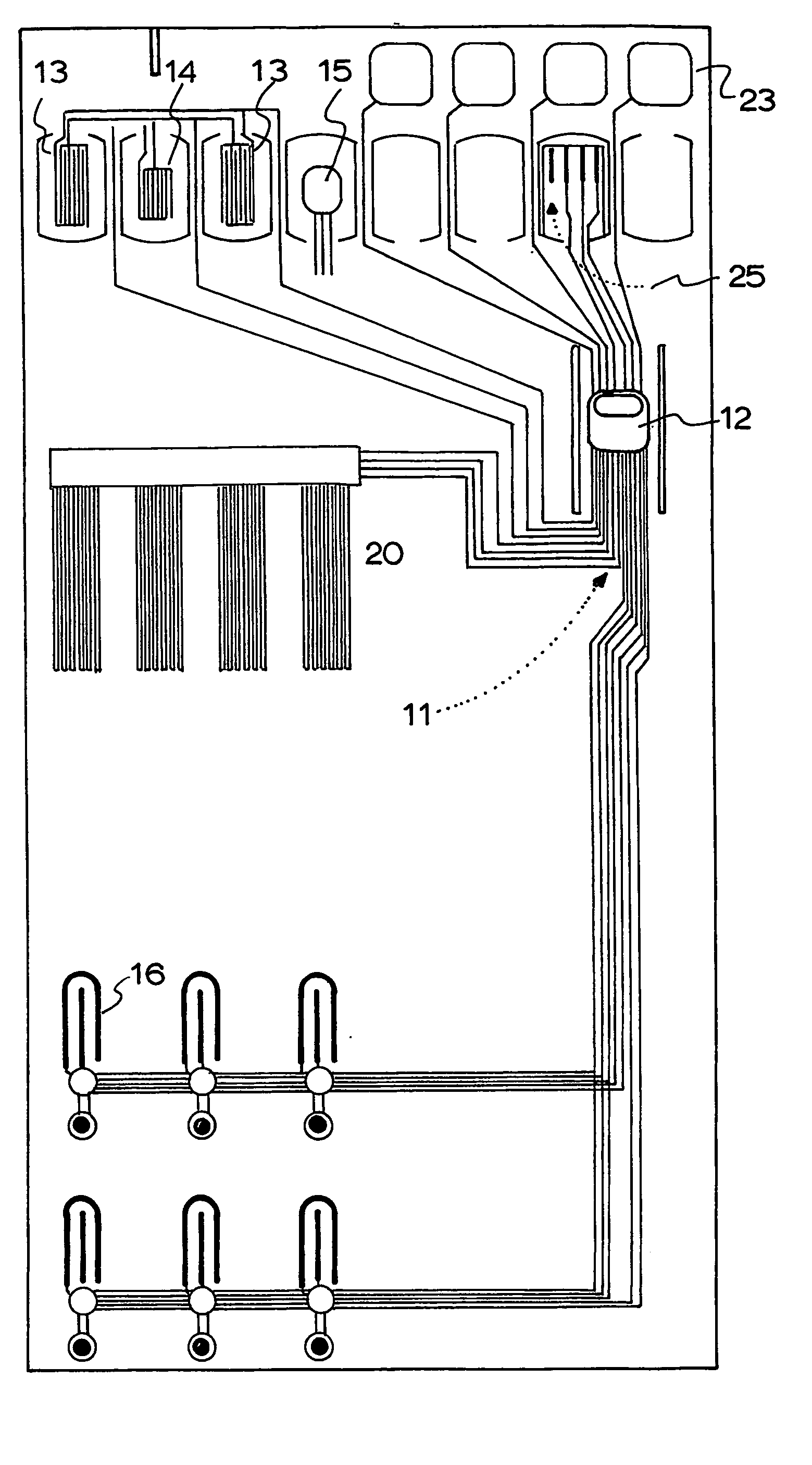
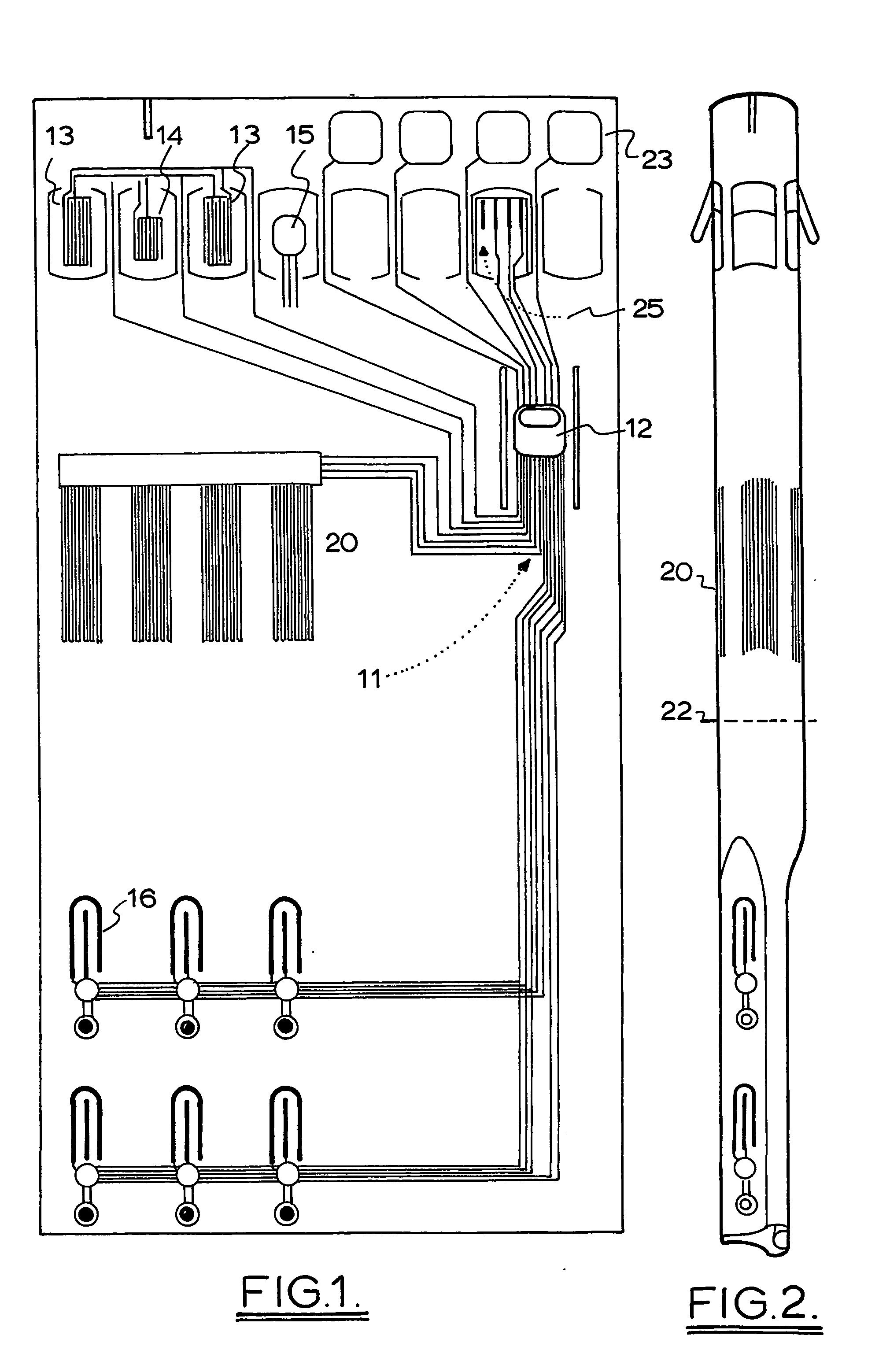
[0030] Ideally the sensor is formed on a flexible polymer substrate by printing the conductive electrodes onto the substrate followed by printing a dielectric layer over both the conductive electrodes. A further conductive layer is then printed over both sides of the entire sensor except for the area immediately over the primary electrode which is to be used to make the measurement. This conductive area must also completely cover all sensor interconnections (wiring). A further improvement can be made by the additional of a dummy sensor's wiring. The wiring should be similar in surface area to that of the other two sensor's wiring but the electrode itself is not present. This trinary sensor then provides information about the parasitic capacitance of the interconnection and electronic components which can then be used to further improve the quality of the measurement. The secondary and trinary sensors can now be used to set upper and lower values for the range of the primary sensor. The two calibration sensors can be used to calibrate a multiple of primary sensors.
[0042] Because the flexible substrate supported sensors are fabricatable by screen printing techniques they lend themselves to inexpensive mass manufacture with the consequent advantage of being relatively low cost. This means that the sensors can be disposable.

Problems solved by technology

Capacitive sensors which are usual in micro devices do have calibration problems.
The sensors discussed above are not suitable for such applications and are usually too expensive.

Method used


Image

  • Environmental sensor
  • Environmental sensor
  • Environmental sensor

Examples


Embodiment Construction

[0045] Some preferred embodiments of the invention will now be described with reference to the drawings in which:

[0046]FIG. 1 is a schematic outline of a multi sensor layout on a flexible substrate;

[0047]FIG. 2 illustrates the multi sensor of figure in rolled into the form of a stake;

[0048]FIG. 3 illustrates the operation of the capacitive moisture sensor used in the multi sensor of FIG. 1;

[0049]FIG. 4 illustrates the layers forming a printed soil sensor;

[0050]FIG. 5 illustrates a plant management system utilizing the sensor array of FIGS. 1 and 2;

[0051]FIG. 6 is a schematic view of a combined silicon based temperature wind and humidity sensor;

[0052]FIG. 7 is a side view of FIG. 5;

[0053]FIG. 8A is a schematic circuit diagram of the sensor of FIG. 5;

[0054]FIG. 8B is a schematic layout of alternative electrical circuits for the wind speed / direction and temperature sensor of FIG. 5;

[0055] FIGS. 9 to 15 illustrate the masks used to fabricate the sensor illustrated in FIG. 6.

[00...


PUM

PropertyMeasurementUnit
thicknessaaaaaaaaaa
temperatureaaaaaaaaaa
temperaturesaaaaaaaaaa

Abstract

Multi functional sensors are described. A silicon based sensor utilizes metal layers arranged as resistors around a central pair if resistors separated by a humidity sensitive polymer with one of the central resistors being a heater. This enables temperature humidity wind speed and direction to be measured. In another embodiment an array of resistors is printed onto a flexible substrate to form the basis of an array of sensors. A soil moisture sensor, which is also useful as a leaf wetness sensor, incorporates a novel self calibrating capacitive sensor structure. The flexible substrate is rolled into a stake that can be inserted in the soil so that below ground sensors measure soil moisture and above ground sensors measure temperature, light, humidity, wind speed and direction.

Description

[0001] This invention relates to sensors for measuring environmental parameters including temperature, humidity, air flow and soil moisture using micro electronic sensors. BACKGROUND TO THE INVENTION [0002] U.S. Pat. Nos. 5,029,101 and 5,117,359 disclose non integrated sensor assemblies for measuring temperature humidity and wind speed. [0003] Airflow sensors using heated resistors and temperature sensors to measure flow are known and typical forms of these are disclosed in U.S. Pat. Nos. 5,108,193 and 57,080,205. [0004] U.S. Pat. No. 6,035,711 discloses a wind sensor utilizing two measuring circuits and four heating elements. [0005] Humidity has been measured as disclosed in U.S. Pat. Nos. 4,965,698 and 505,434 by measuring variations in capacitance using a polyimide film. [0006] Combination sensors have also been proposed. U.S. Pat. No. 5,918,110 discloses a combination pressure and electrochemical sensor. U.S. Pat. 5,929,344 discloses a multiple resistive temperature sensors whic...

Claims


Application Information

Patent Timeline
Patent Type & Authority Applications(United States)
IPC IPC(8): G01R27/26A01G25/16G01D21/02G01F1/684G01F1/692G01N27/22G01P5/12G01P13/02
CPCA01G25/167G01D21/02G01F1/6845G01N33/246G01N27/223G01P5/12G01P13/02G01F1/692
Inventor TANNER, PHILIPJOHNSON, PETERTHIEL, DAVIDSUZUKI, TAKEHARUADAMEC, RICHARDBEADLE, PETER HENRY WILLIAM
Owner M B T L
Learn More