Processes and apparatus for the production of chlorine by gas phase oxidation

a technology of gas phase oxidation and process equipment, which is applied in the preparation of chlorides, physical/chemical process catalysts, metal/metal-oxide/metal-hydroxide catalysts, etc., can solve the problems of permanent damage to the catalyst, impairment of yield, and difficulty in maintaining a constant temperature in the catalyst bed, so as to simplify the process design and operation

Inactive Publication Date: 2007-11-29
COVESTRO DEUTSCHLAND AG
View PDF10 Cites 24 Cited by
  • Summary
  • Abstract
  • Description
  • Claims
  • Application Information

AI Technical Summary

Benefits of technology

[0021] An advantage of adiabatic processes according to the invention, as compared to conventional isothermal procedures, is that mechanisms for the removal of heat do not have to be provided in the catalyst beds, and thus, considerable simplification of the process design and operation can be achieved in use. This additionally provides simplification when manufacturing reactor systems and w

Problems solved by technology

An uncontrolled rise in temperature, that can amount to 600 to 900° C. from start to finish of the Deacon reaction, can lead on the one hand to permanent damage to the catalyst and, on the other hand, to an unfavourable shift of the reaction equilibrium in the direction of the feedstocks at high temperatures, with a corresponding impairment in the yield.
However, problems with maintaining a constant temperature in the catalyst beds can arise in such reactors.
Thermostated, multitube-flow reactors are generally used as a result, but these reactors usually have a very costly cooling circuit, particularly in the case of large reactors.
However, even in the event of high thermal conductivity within the catalyst pellets, since the thermal conductivity of the bed can still be low, the removal of heat is not substantially improved by such measures.
The disadvantages of such a process are that two or more catalyst systems have to be developed and used in the contact tubes and that the capacity of the reactor is impaired by the use of an inert material.
Thus, it is not at all clear how the heat of reaction can be removed from the exothermic reaction and

Method used


Image

  • Processes and apparatus for the production of chlorine by gas phase oxidation
  • Processes and apparatus for the production of chlorine by gas phase oxidation

Examples


example 1

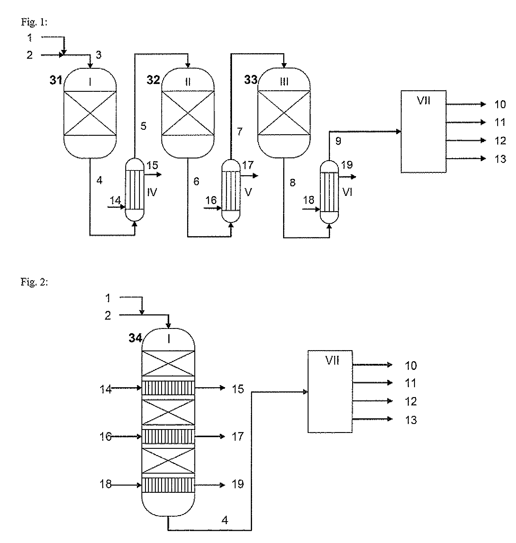
[0084]FIG. 1 shows a process according to one embodiment of the invention with three catalyst beds in series divided between three separate reactors. The feedstock gases are mixed upstream of the first reactor and supplied to the reactor. After each of the reactors, the emerging reaction gas is cooled using a shell-and-tube heat exchanger of the conventional type. After emerging from the third heat exchanger, chlorine and water are separated from the product gas.

example 2

[0085]FIG. 2 shows a process according to another embodiment of the invention with three catalyst beds in series in an integrated reactor. The feedstock gases are mixed upstream of the reactor and fed to this reactor. Following each of the catalyst beds, the emerging process gas is cooled using a heat exchanger also integrated in the pressurised container for the reactor. After emerging from the reactor, chlorine and water are separated from the product gas.

example 3

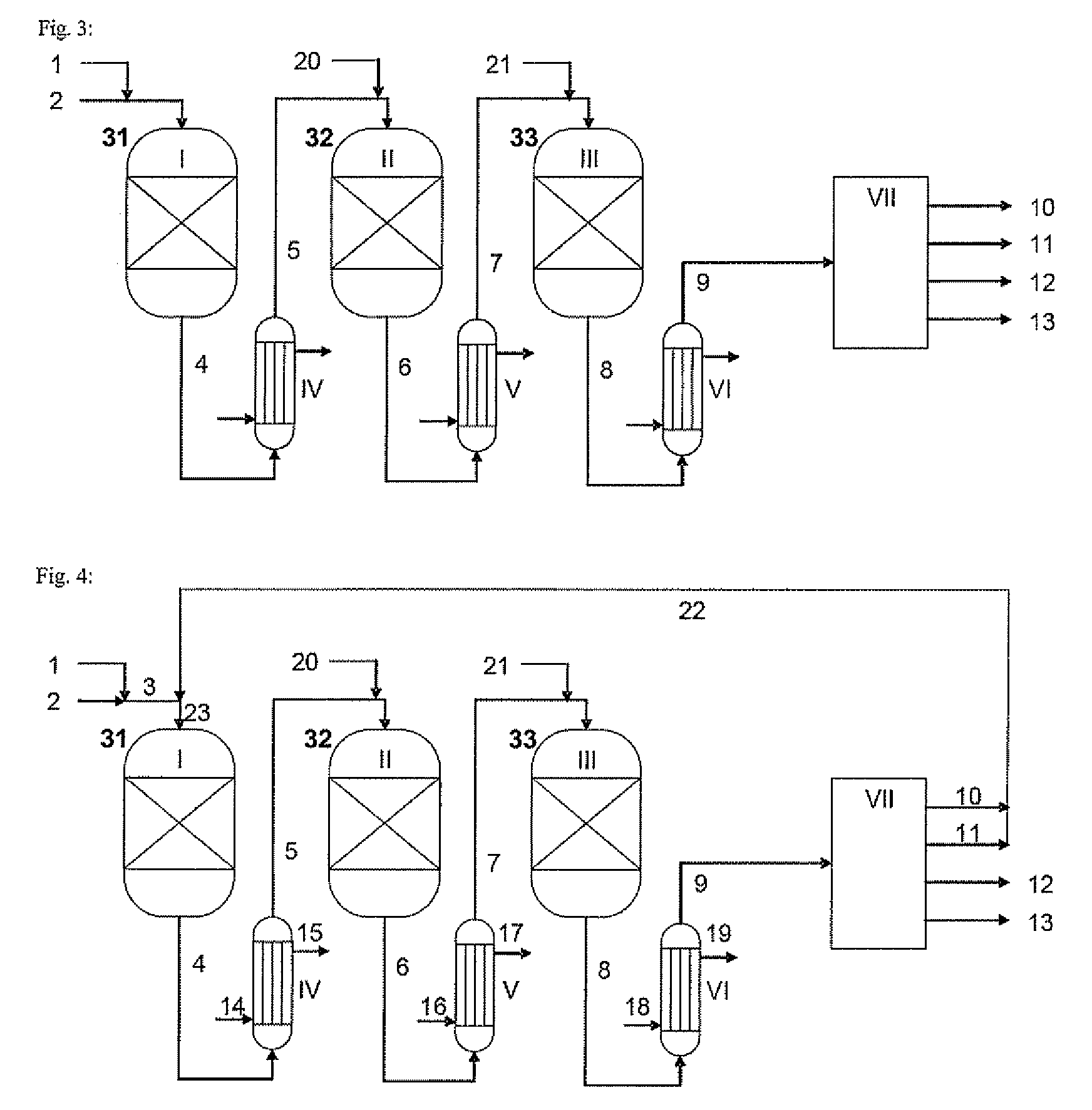
[0086]FIG. 3 shows a process according to another embodiment of the invention with a layout that corresponds by and large to the one shown in FIG. 1. The difference is that, upstream of the second and third reactors in series, fresh feedstock gas is introduced into the cooled process gas from the preceding reactor.


PUM

PropertyMeasurementUnit
Temperatureaaaaaaaaaa

Abstract

The present invention provides a process for producing chlorine by the catalytic gas phase oxidation of hydrogen chloride with oxygen, wherein the reaction is performed on at least two catalyst beds under adiabatic conditions, as well as a reactor system for performing the process.

Description

BACKGROUND OF THE INVENTION [0001] A basic process for the catalytic oxidation of hydrogen chloride with oxygen in an exothermic equilibrium reaction, developed by Deacon in 1868, was devised at the very beginning of industrial chlorine chemistry: 4HCl+O2⇄2Cl2+2H2O [0002] However, chloroalkali electrolysis pushed the Deacon process right into the background. A significant amount of chlorine production was achieved using the electrolysis of aqueous common salt solutions. The attractiveness of the Deacon process has increased in more recent times, however, because the worldwide requirement for chlorine is growing more strongly than the demand for caustic soda solution, an associated by-product from electrolysis processes. A process for producing chlorine by the oxidation of hydrogen chloride that is independent of the production of caustic soda solution, such as a Deacon process, fits in with this development. In addition, the hydrogen chloride reactant needed for such oxidation proce...

Claims


Application Information

Patent Timeline
IPC IPC(8): C01B7/04B01J8/04
CPCB01J8/0453B01J8/0457B01J8/0496B01J23/462C01B7/04B01J2208/00168B01J2208/00176B01J2208/00274B01J2219/0004B01J27/13B01J23/46
Inventor WOLF, AURELMLECZKO, LESLAWSCHUBERT, STEPHANSCHLUTER, OLIVER FELIX-KARL
Owner COVESTRO DEUTSCHLAND AG
Why Eureka
Try Eureka