Linear generator

Inactive Publication Date: 2007-12-06
GALICH THOMAS P
View PDF25 Cites 25 Cited by
  • Summary
  • Abstract
  • Description
  • Claims
  • Application Information

AI Technical Summary

Benefits of technology

[0014]The linear generator may includes a plurality of sets of inductive coils and permanent magnets arranged side by side in a single row or as an array that includes multiple rows or layers each comprising a plurality sets of inductive coils and permanent magnets. To save the space or area, the inductive coils and the permanent magnets can also be arranged along a cylindrical profile. The arrangement flexibility allows the linear generator to be configured in a wide range of sizes adapted for powering a wide range of inhabitable structures including residences, commercial facilities, factories and vehicles. For example, the linear generator can be installed in a vehicle such as a car or a truck, such that the vehicle can be operated by electric power instead of fuel. While applying in a factory or a power plant where large power is often required, multiple rows or layers of inductive coils a

Problems solved by technology

As it is well known that these fuels are non-renewable and their supply can be ultimately exhausted.
In addition to the limited supply, the burning of fossil fuels produces unwanted byproducts such as sulfur dioxide, carbon dioxide, and oxides of nitrogen.
Scientists have proven that such byproducts are hazardous to the environment as well as to human health.
However, none of the alternative energy sources has been commonly adapted because of their complexity and associated high costs.
However, solar power electricity generation systems are typically very expensive to build and maintain.
The large costs of solar power systems are therefore often prohibitive.
The main drawback to geothermal energy is that it is dependent upon geographical location and, thus, it is not readily available throughout the wor

Method used


Image

  • Linear generator
  • Linear generator
  • Linear generator

Examples


Embodiment Construction

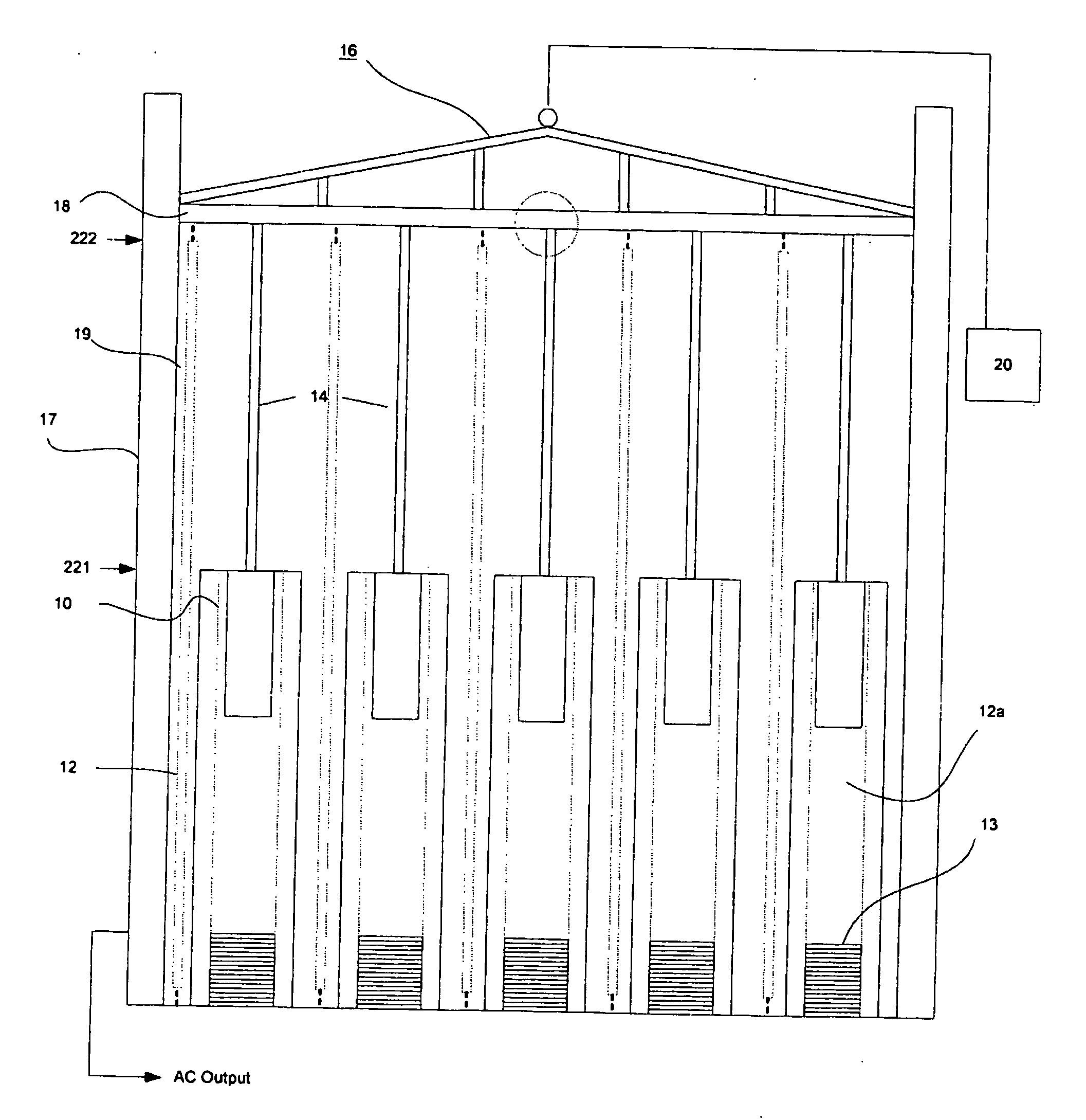
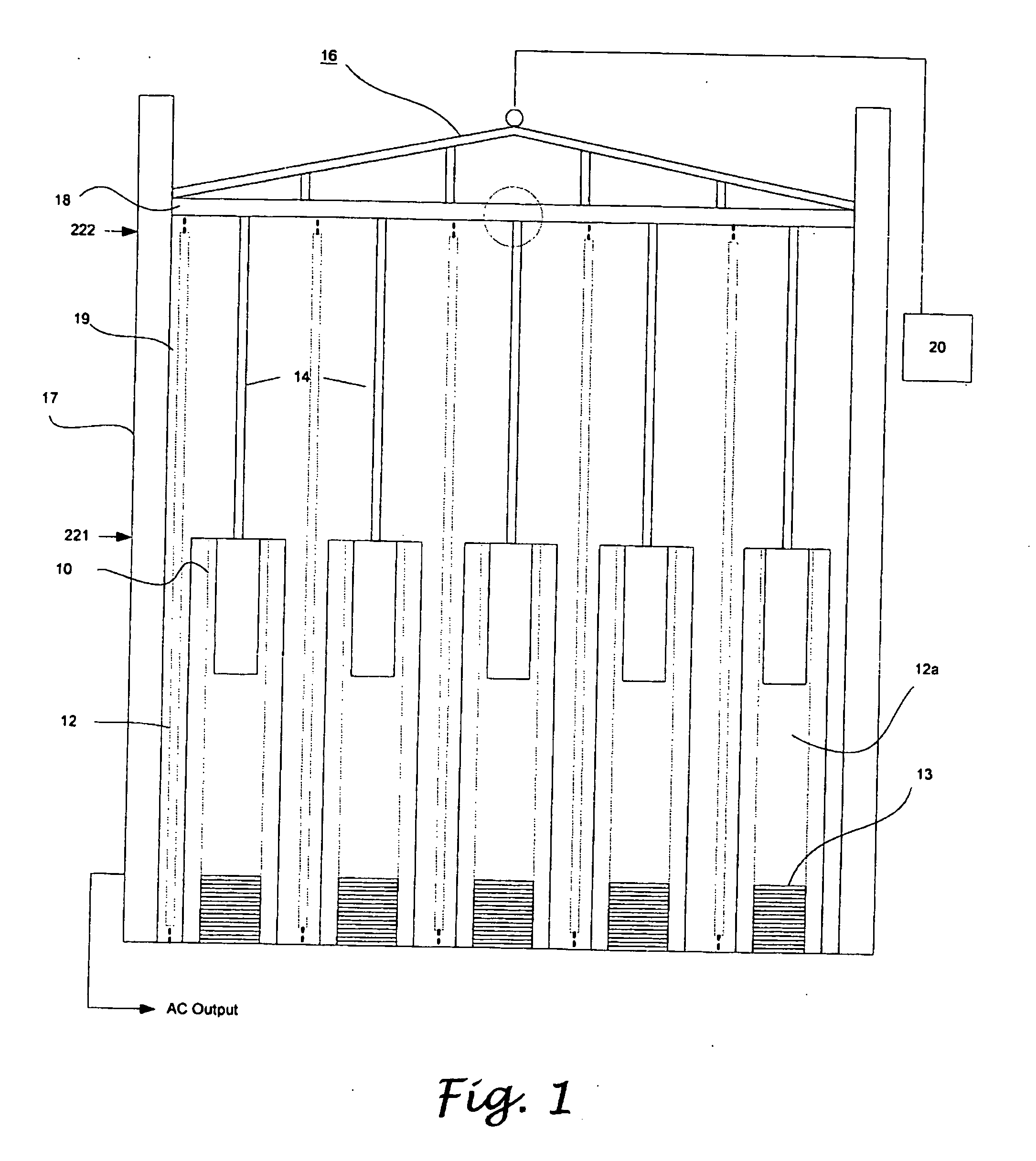
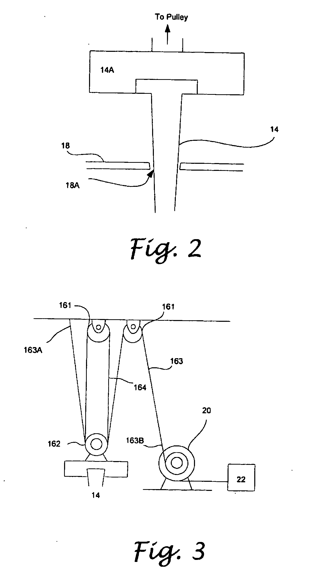
[0028]A linear generator producing AC or DC electric energy by reciprocally movement of magnets between two opposing ends of induction coils is provided and illustrated in FIG. 1. As shown, the linear generator includes a plurality of inductive coils 12 and a plurality of magnets 10 supported and enclosed by a frame or housing (17 and 18), an electric motor 20 for generating a lifting force to the magnets 10, and a pulley assembly 16 connecting the magnets 10 to the electric motor 20 and providing a mechanical advantages. Each of the conductive coils 12 defines a channel 12a allowing the magnets 10 to move through in either direction. The top end of each magnet 10 is connected to the pulley assembly 16 via a rigid rod, string, or cable 14. When the magnets 10 are located at the top portion of the channels 12a, the gravity drives the magnets 10 moving downwardly through the channels 12a. When the magnets 10 reach the bottom portion of the channels 12a, the pulley electric motor 20 ge...


PUM


Abstract

A linear generator which generates electric energy by reciprocal movement of magnets with inductive coils is provided. The linear generator has a plurality of elongate inductive coils, a plurality of magnets inserted into the respective inductive coils and slidable between two opposing ends of the inductive coils, a pulley assembly connected to top ends of the magnets, and an elevating motor generating and applying a lifting force to the magnets through the pulley assembly. The pulley assembly is operative to provide 1:N mechanical advantage, where N is preferably an even integer larger than 1. The pulley assembly is connected to the magnets by a plurality of rigid cables, rods, or strings, and a cable connected to the elevating motor is reeved through the pulley assembly, so as to exert a lifting force to the magnets via the pulleys.

Description

CROSS-REFERENCE TO RELATED APPLICATIONS[0001]Not ApplicableSTATEMENT RE: FEDERALLY SPONSORED RESEARCH / DEVELOPMENT[0002]Not ApplicableBACKGROUND[0003]The present invention relates in general to an electrical energy generator, and more particularly, to a linear generator which generates either alternate (AC) or direct current (DC) electrical energy by the reciprocal movement of permanent magnets through inductive coils.[0004]Currently, fossil fuels or hydrocarbons are the main source of fuel for electrical energy generation. As it is well known that these fuels are non-renewable and their supply can be ultimately exhausted. In addition to the limited supply, the burning of fossil fuels produces unwanted byproducts such as sulfur dioxide, carbon dioxide, and oxides of nitrogen. Scientists have proven that such byproducts are hazardous to the environment as well as to human health. Thus, in attempts to conserve the limited supply of non-renewable fossil fuels, alternative energy sources...

Claims


Application Information

Patent Timeline
IPC IPC(8): H02K7/18F03G7/08F02B63/04
CPCH02K7/1876F03G7/08
Inventor GALICH, THOMAS P.
Owner GALICH THOMAS P
Why Eureka
Try Eureka