
Signal Output Circuit, Audio Signal Output Apparatus Using The Same, And Electronic Device

a technology of audio signal and output circuit, applied in pulse manipulation, pulse technique, instruments, etc., can solve the problems of insufficient reduction of set size, inability to make output gradually rise at the start of operation, inrush current irritates the auditory sense, etc., and achieves the effect of restricting noise and reducing circuit area

Inactive Publication Date: 2007-12-06
ROHM CO LTD
View PDF5 Cites 13 Cited by
  • Summary
  • Abstract
  • Description
  • Claims
  • Application Information

AI Technical Summary

Benefits of technology

[0009] The present invention has been made in view of these problems and an object thereof is to provide a signal output circuit that restricts the noise due to an inrush current and reduces the circuit area.
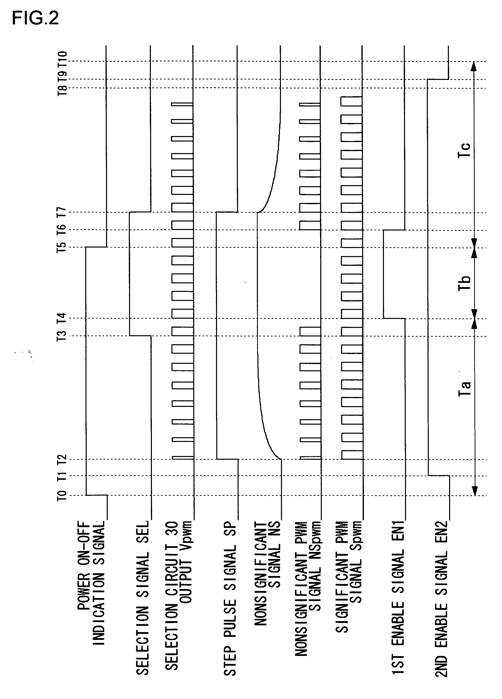
[0011] According to this embodiment, a ancillary signal for use with soft start is amplified by the second driver circuit at power-on or power-off, at which time the noise occurs. Thereby the inrush current can be suppressed and the noise can be reduced.
[0016] The load driving capability of the second driver circuit is set lower than that of the first driver circuit by adjusting the resistance element provided in series in the output of the second driver circuit or adjusting the transistor size, so that the noise level can be effectively suppressed. Furthermore, when the primary signal is reproduced by the first driver circuit, the effect of the second driver circuit can be made smaller.
[0018] According to this embodiment, at power-on, the timing of signal selection by the selection circuit and the on-off switching of the first driver can be arbitrarily adjusted by the control circuit, so that the noise can be effectively suppressed.
[0023] According to this embodiment, the noise can be suppressed from being occurring from a speaker at power-on or power-off.

Problems solved by technology

Though this high-order ΣΔ modulator exceeds in pushing out the quantization noise beyond the human audible band, it is characterized by that the output cannot be made to gradually rise up at the start of operation.
This inrush current irritates the auditory sense as undesirable noise from a speaker or headphone.
In addition, the mute control terminals and the connections around them are required, causing a problem in that the demand for reduced size of a set is not met.

Method used


Image

  • Signal Output Circuit, Audio Signal Output Apparatus Using The Same, And Electronic Device
  • Signal Output Circuit, Audio Signal Output Apparatus Using The Same, And Electronic Device
  • Signal Output Circuit, Audio Signal Output Apparatus Using The Same, And Electronic Device

Examples


Embodiment Construction

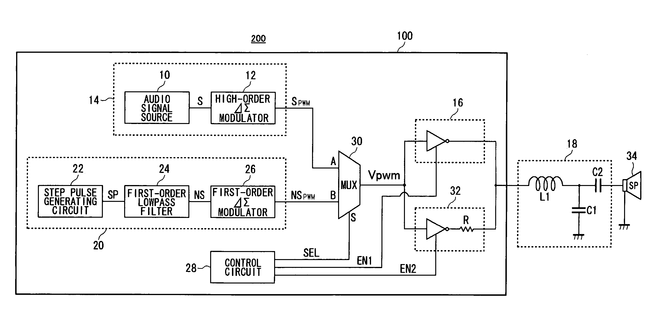
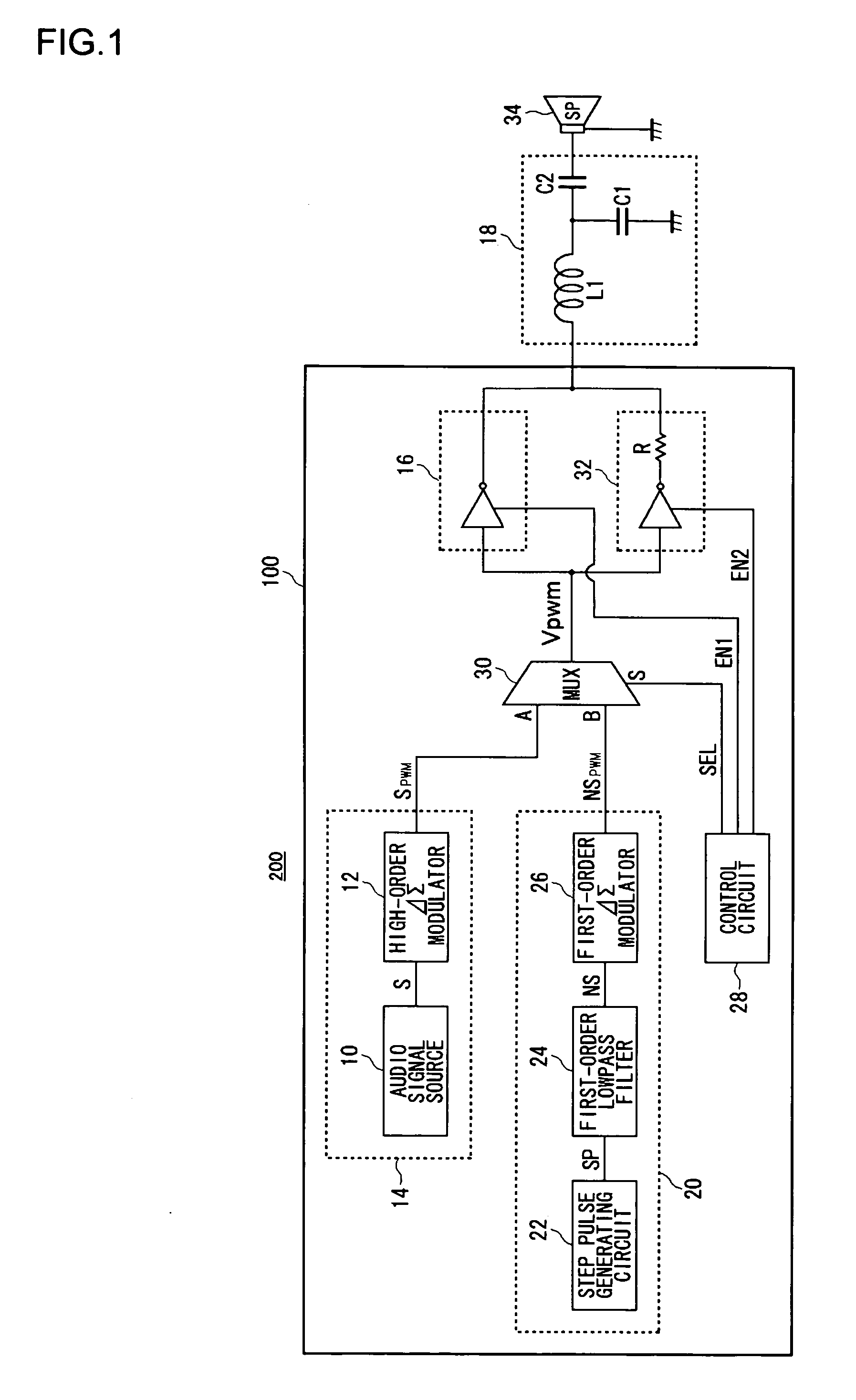
[0027] An embodiment of the present invention will be described with reference to FIG. 1. FIG. 1 is a circuit diagram showing a structure of an audio signal output apparatus 200 using a signal output circuit 100 according to an embodiment of the present invention.

[0028] An audio signal output apparatus 200 is installed in electronic equipment provided with audio output means such as a CD player or MD player, and includes a signal output circuit 100, a post lowpass filter 18 and a speaker 34. The signal output circuit 100 is a so-called digital amplifier, and outputs digital signals which have undergone pulse width modulation. The speaker 34 may be an earphone, a headphone or the like.

[0029] The post lowpass filter 18 includes a series inductor L1, a shunt capacitor C1 and a DC block capacitor C2. The post lowpass filter 18 removes the high-frequency components and DC components of digital signals outputted from the signal output circuit 100. This post lowpass filter 18 converts a ...


PUM


Abstract

A selection circuit switches the output between a ancillary PWM signal NSPWM and a primary PWM signal SPWM in accordance with a power supply transition period or normal period. A ancillary signal generating circuit generates a gradually rising signal which is then amplified by a second driver circuit, so that a DC block capacitor is gradually charged and discharged. Thereby, the occurrence of noise due to an inrush current is prevented.

Description

TECHNICAL FIELD [0001] This invention relates to a signal output circuit, and it particularly relates to a signal output circuit having a function of preventing the occurrence of noise arising from an abrupt change in voltage waveforms at power-on or power-off. BACKGROUND TECHNOLOGY [0002] In recent years of development done in the LSI technology, the 1-bit DAC (Digital Analog Converter) are used for the digital signal processing and the amplification thereof in the digital audio represented by CD players, MD players and the like. In this 1-bit DAC, the audio signals undergo the noise shaping by the use of a ΣΔ modulator and are then outputted as 1-bit signals which have been subjected to pulse-width modulation PWM (Pulse Width Modulation). [0003] The 1-bit PWM signal is amplified to a predetermined level in order to drive a speaker which is a load. In so doing, a Class D amplifier by which high efficiency can be obtained is used. The amplified 1-bit PWM signal passes through a post...

Claims


Application Information

Patent Timeline
Patent Type & Authority Applications(United States)
IPC IPC(8): H03K5/00H03F1/00H03F1/26H03F3/217
CPCH03F1/26H03F3/217H03F2200/372H03F2200/331H03F2200/351H03F2200/03H03F3/20
Inventor ONODERA, TAKESHIMUNENAGA, HIDEKISAKAIDANI, SATOSHI
Owner ROHM CO LTD
Learn More