Bridgeless pfc converter with low common-mode noise and high power density

a converter and bridgeless technology, applied in the direction of electric variable regulation, process and machine control, instruments, etc., can solve the problems of low conversion efficiency of converters, poor reverse recovery characteristics, and low common-mode noise of converters, so as to reduce common-mode noise and enhance the power density of converters

Active Publication Date: 2007-12-06
DELTA ELECTRONICS INC
View PDF3 Cites 87 Cited by
  • Summary
  • Abstract
  • Description
  • Claims
  • Application Information

AI Technical Summary

Benefits of technology

[0008]An object of the present invention is to provide a power factor correction circuit using a bridgeless boost converter to implement, which can reduce the common-mode noise existed in the circuit and enhance the power density of the converter.

Problems solved by technology

However, the rectifying diodes that constitute the bridge rectifier BR are inevitable to cause considerable conduction loss.
As a result, the conversion efficiency of the converter is degraded.
Nonetheless, the parasite diodes on the transistor switches Q21 and Q22 of the converter shown in FIG. 2 are configured to switch at a high frequency, and their reverse recovery characteristics are quite bad.
In practical applications, the converter is prone to lose the advantage of low common-mode noise due to the high switching frequency or the persistent operation in discontinuous conduction mode (DCM).
The major disadvantage of the converter shown in FIG. 3 is that power bounce would occur between the input voltage and the output voltage.
More disadvantageously, the common-mode noise would be augmented with the increase of the parasitical capacitance value between the buses and ground.
Nonetheless, the boost inductors L41, L41 would cause a waste of circuit board space due to its bulky dimensions.
Also, the boost inductors L41, L42 are operating in an alternate manner during the time period of the input AC voltage Vin, which would result in a low utilization of the boost inductors L41, L42 and become difficult to improve the power density.

Method used


Image

  • Bridgeless pfc converter with low common-mode noise and high power density
  • Bridgeless pfc converter with low common-mode noise and high power density
  • Bridgeless pfc converter with low common-mode noise and high power density

Examples


second embodiment

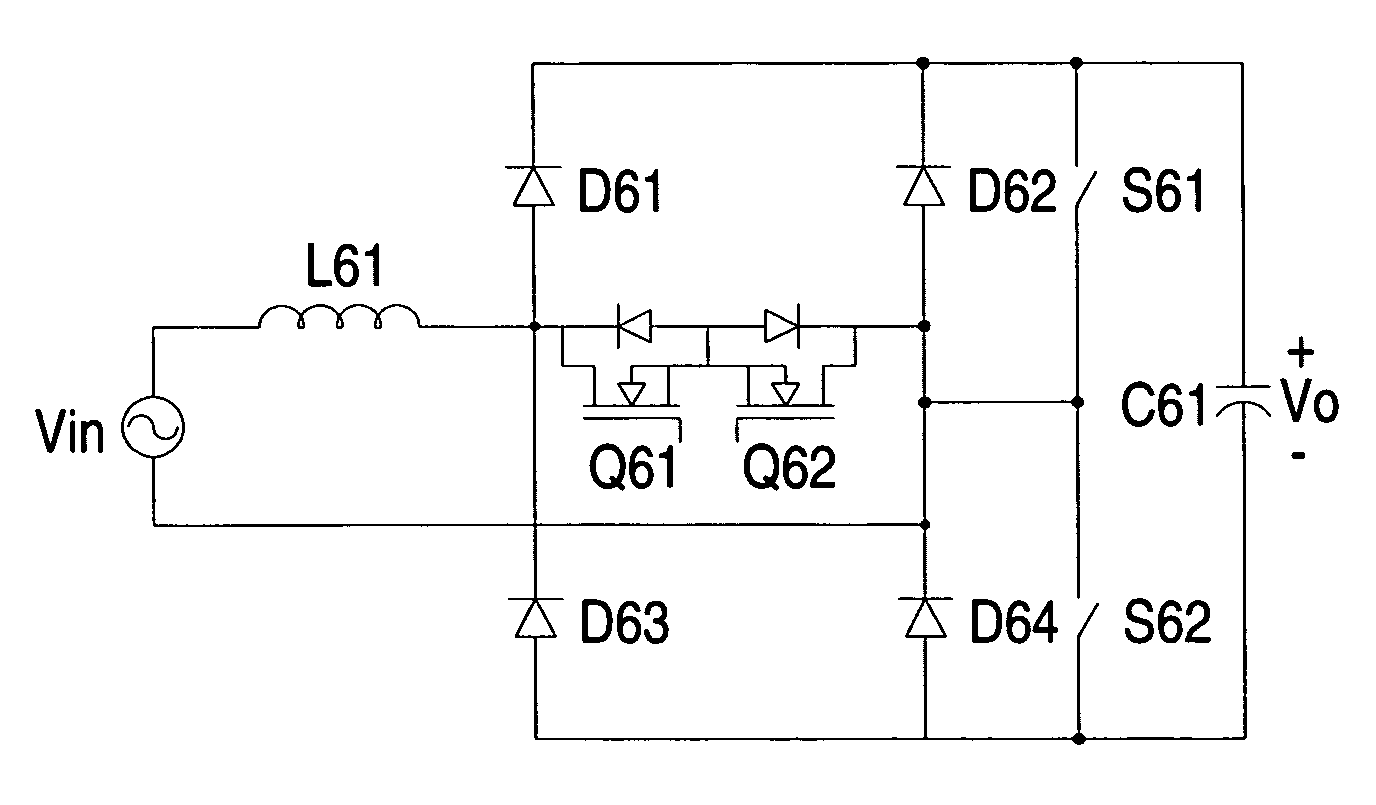
[0033]FIG. 6 is a circuit diagram of the bridgeless power factor correction converter according to the present invention. The configuration and operation of the boost inductor L61, the bidirectional switch (Q61, Q62), the first series rectifier circuit (D61, D63), the second series rectifier circuit (D62, D64), and the output capacitor C61 are the same with the configuration and operation of the boost inductor L51, the bidirectional switch (Q51, Q52), the first series rectifier circuit (D51, D53), the second series rectifier circuit (D52, D54), and the output capacitor C51 of FIG. 5, and it is not intended to give details herein. Compared with FIG. 5, the converter of FIG. 6 adds a pair of auxiliary switches (S61, S62) which are connected in parallel with the second series rectifier circuit (D62, D64) and configured to switch in synchronization with the frequency of the input AC voltage Vin and thereby suppressing the common-mode noise of the converter with better efficiency.

third embodiment

[0034]FIG. 7 is a circuit diagram of the bridgeless power factor correction converter according to the present invention. The configuration and operation of the boost inductor L71, the bidirectional switch (Q71, Q72), the first series rectifier circuit (D71, D73), the second series rectifier circuit (D72, D74), and the output capacitor C71 are the same with the configuration and operation of the boost inductor L51, the bidirectional switch (Q51, Q52), the first series rectifier circuit (D51, D53), the second series rectifier circuit (D52, D54), and the output capacitor C51 of FIG. 5, and it is not intended to give details herein. Compared with FIG. 5, the converter of FIG. 7 adds a pair of auxiliary capacitors (C72, C73) which are connected in parallel with the second series rectifier circuit (D72, D74) and configured to further suppress the common-mode noise by its low-impedance characteristics at high frequencies. Alternatively, with the equivalent characteristic of the capacitor ...

fourth embodiment

[0035]FIG. 8 is a circuit diagram of the bridgeless power factor correction converter according to the present invention. The bridgeless power factor correction converter of FIG. 8 is an interleaved power converter circuit, in which a first boost inductor L81, a first bidirectional switch (Q81, Q82), a first series rectifier circuit (D81, D82), and a second series rectifier circuit (D83, D84) form a first power converter stage having the same topology with the bridgeless power factor correction converter of FIG. 5, and a second first boost inductor L82, a second bidirectional switch (Q83, Q84), a third series rectifier circuit (D85, D86), and the second series rectifier circuit (D83, D84) form a second power converter stage having the same topology with the bridgeless power factor correction converter of FIG. 5. The bridgeless power factor correction converter of FIG. 8 is derived by interleaving a bridgeless power factor correction converter of FIG. 5 with another bridgeless power ...


PUM


Abstract

A bridgeless power factor correction converter that can reduce common-mode noise and enhance power density is made up of a boost inductor coupled to an input end, a bidirectional switch connected in series with the boost inductor, a first series rectifying circuit having a junction node connected between the boost inductor and the bi-directional switch, a second series rectifying circuit connected in parallel with the first series rectifying circuit and having a junction node coupled to the bi-directional switch, and an output capacitor connected in parallel with the second series rectifying circuit, in which the second series rectifying circuit is made up of slow-recovery diodes and the first series rectifying circuit is made up of fast-recovery diodes.

Description

FIELD OF THE INVENTION[0001]The present invention is related to a power factor correction converter, and more particularly to a bridgeless power factor correction converter capable of reducing common-mode noise and enhancing power density.BACKGROUND OF THE INVENTION[0002]Switching power supply is a power conversion circuit that uses switching operations to convert an input voltage waveform into a specific output voltage waveform. A boost converter is an example of switching power supply that can provide power factor correction and total harmonic distortion reduction to the input voltage and convert the input voltage into a stable and regulated output voltage.[0003]FIG. 1 is a circuit diagram of a well-known power factor correction (PFC) boost converter according to the prior art. In FIG. 1, a bridge rectifier BR is connected to an input AC voltage Vin for converting the input AC voltage Vin into a full-wave rectified DC voltage. A boost inductor L11 is connected to an output termina...

Claims


Application Information

Patent Timeline
Patent Type & Authority Applications(United States)
IPC IPC(8): H02M7/00
CPCH02M1/4208Y02B70/126H02M1/4225Y02B70/10Y02P80/10H02M1/0043H02M1/0085
Inventor LIU, TENGXIN, XIAONIZENG, JIANHONGYING, JIANPINGZHAO, WEI
Owner DELTA ELECTRONICS INC
Why Eureka
Try Eureka