Bioanalytical instrumentation using a light source subsystem

Active Publication Date: 2007-12-06
LUMENCOR
View PDF99 Cites 62 Cited by
  • Summary
  • Abstract
  • Description
  • Claims
  • Application Information

AI Technical Summary

Benefits of technology

[0029] In an embodiment of the present invention, a luminescence and collection system can irradiate homogeneous reactions within fluidic conduits or reservoirs; to irradiate heterogeneous reactions on the surface of fluidic conduits or reservoirs; to irradiate homogeneous or heterogeneous reactions on the surface of or within the pores of a porous reaction support.
[0030] In an embodiment of the present invention, a luminescence and collection system can emit multiple colors as desired. In an embodiment of the present invention, a luminescence and collection system can be pulsed on and off as de

Problems solved by technology

However, the lamps and lasers that power these bioanalytical systems have presented engineering and cost constraints that limit sensitivity, reproducibility and robustness.
Typically lamps produce broad-spectrum spontaneous emission but due to their large angular output collection efficiency is poor.
Large power densities are difficult to attain; moreover accessing discrete wavelengths using filters

Method used


Image

  • Bioanalytical instrumentation using a light source subsystem
  • Bioanalytical instrumentation using a light source subsystem
  • Bioanalytical instrumentation using a light source subsystem

Examples


Embodiment Construction

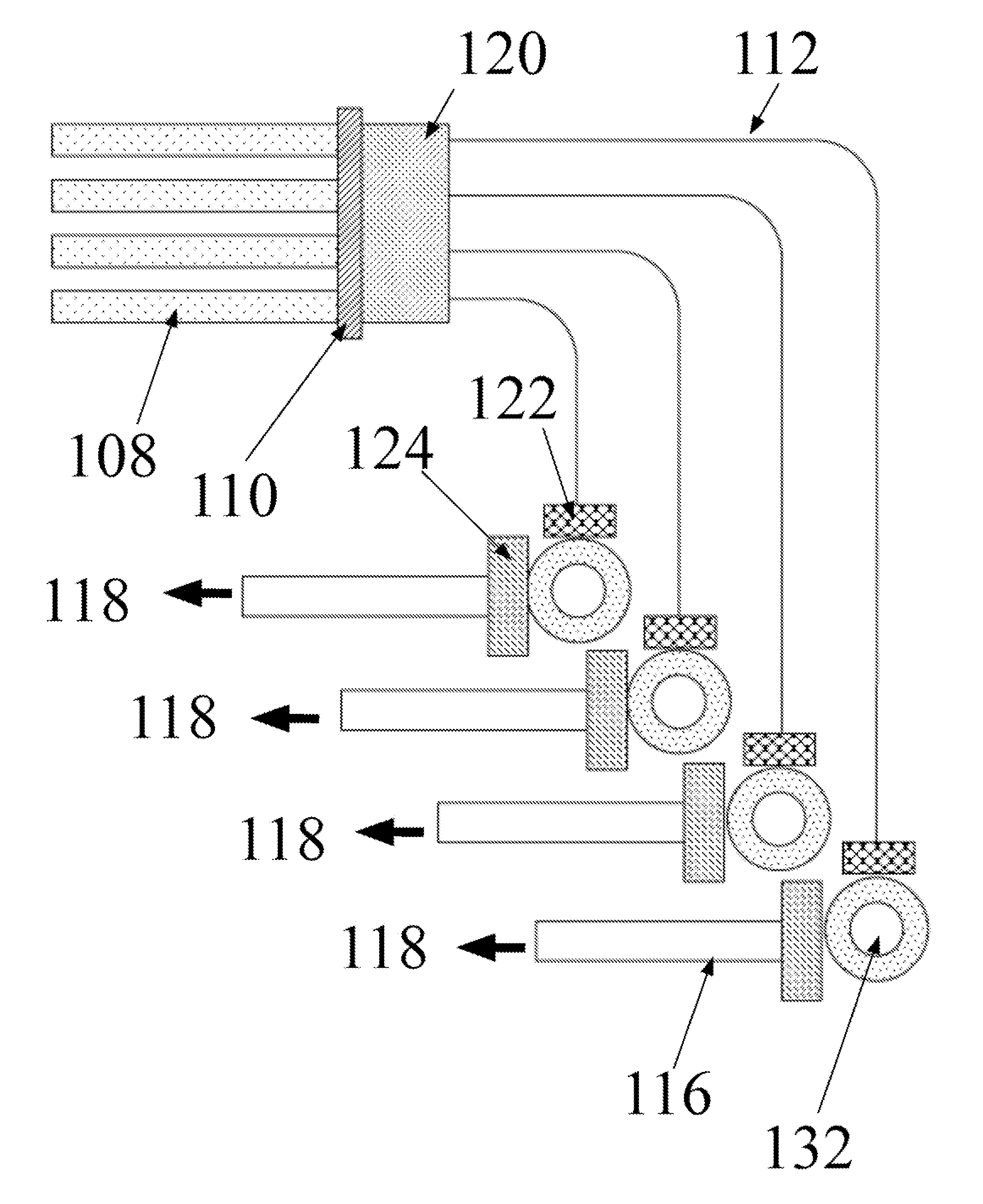
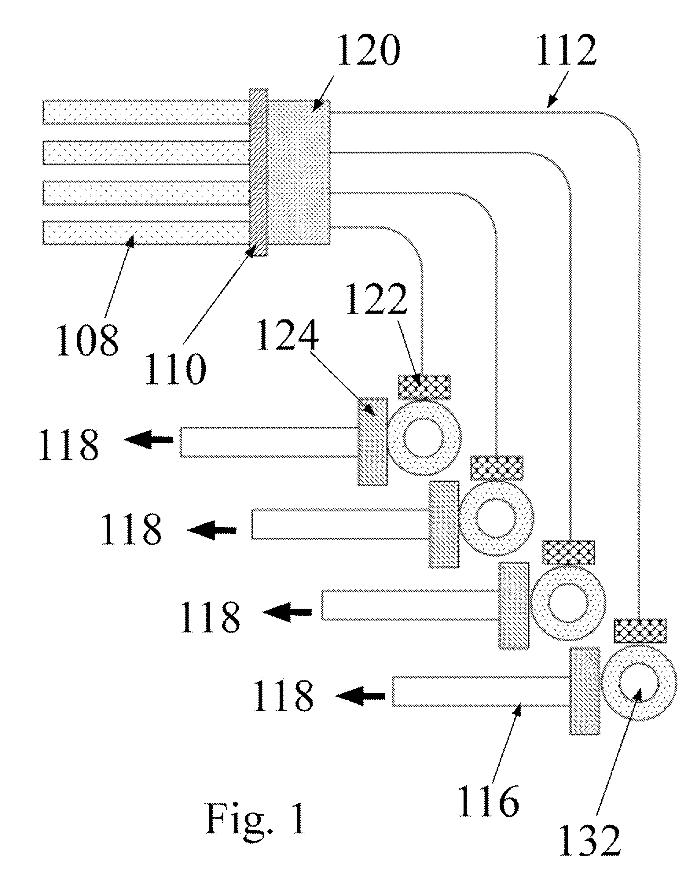
[0054] The detection volume in the form of a well of fluid, a spot of fluid, a channel containing fluid or a reservoir attached to a channel containing fluid will all be referred to herein as the “detection volume”. The term “detection volume” can also refer to any of the afore mentioned constructs in which the reaction for detection occurs in freely diffusing solution, in a gel or polymer, attached to a surface, contained within a pore, or in some subsection of the entire well volume. As seen in FIG. 9, one example of the present invention comprises a plurality of lamps (908) with filters (910) for selecting the wavelength of choice, in conjunction with a device for coupling (920) the lamps into multiple optical fibers, multiple optical fibers for transferring the excitation light to the wells, adapters for coupling light from the fibers into the detection volumes (914) located in a microtiter plate (924) and for coupling fluorescence from the detection volumes into collection fibe...


PUM

PropertyMeasurementUnit
Nanoscale particle sizeaaaaaaaaaa

Abstract

The invention relates to a light source for irradiating molecules present in a detection volume with one or more selected wavelengths of light and directing the fluorescence, absorbance, transmittance, scattering onto one or more detectors. Molecular interactions with the light allow for the identification and quantitation of participating chemical moieties in reactions utilizing physical or chemical tags, most typically fluorescent and chromophore labels. The invention can also use the light source to separately and simultaneously irradiate a plurality of capillaries or other flow confining structures with one or more selected wavelengths of light and separately and simultaneously detect fluorescence produced within the capillaries or other flow confining structures. In various embodiments, the flow confining structures can allow separation or transportation of molecules and include capillary, micro bore and milli bore flow systems. The capillaries are used to separate molecules that are chemically tagged with appropriate fluorescent or chromophore groups.

Description

PRIORITY CLAIM [0001] This application claims priority to: (1) U.S. Provisional Patent Application Ser. No: 60 / 802,883, entitled: “CAPILLARY ELECTROPHORESIS LIGHT PIPE”, inventors: Claudia B. Jaffe et al., filed May 22, 2006; (2) U.S. Provisional Patent Application Ser. No: 60 / 831,011, entitled: “WELL LIGHT PIPE”, inventors: Claudia B. Jaffe et al., filed Jul. 14, 2006 and (3) U.S. States Provisional Patent Application Ser. No: 60 / 888,902, entitled: “CAPILLARY ELECTROPHORESIS LIGHT SOURCE SUBSYSTEM”, inventors: Claudia B. Jaffe et al., filed Feb. 8, 2007. These applications are herein expressly incorporated by reference in their entireties.FIELD OF THE INVENTION [0002] The present invention relates to luminescence systems for irradiating bioanalytical instrumentation including wells containing chemicals for inducing reactions or detecting reactants or products of chemical reactions. The bioanalytical instrumentation can include a light source and fiber optic systems for irradiating ...

Claims


Application Information

Patent Timeline
IPC IPC(8): G01N33/53G01J3/427
CPCG01J3/10G01N21/253G01N21/255G01N21/4788G01N21/51G01N2201/06193G01N21/6452G01N2021/6419G01N2021/6469G01N2021/6484G01N21/53
Inventor JAFFE, CLAUDIA B.JAFFE, STEVEN M.JONES, MICHIEAL L.
Owner LUMENCOR
Why Eureka
Try Eureka