Stent for Vessel

a technology for stents and living bodies, applied in the field of stents for living bodies, can solve the problems of imposing a severe load on patients, not desirable or proper to remain semi-permanently in the living body, etc., and achieve the effect of superior mass-producibility and ease of manufactur

Active Publication Date: 2007-12-06
IGAKI IRYO SEKKEI
View PDF12 Cites 31 Cited by
  • Summary
  • Abstract
  • Description
  • Claims
  • Application Information

AI Technical Summary

Benefits of technology

[0034] In addition, since the tubular body is formed by combining plural stent constituting members having the tubular-body forming elements comprising part of a tubular body, the stent for a vessel may be manufactured with ease and

Problems solved by technology

Hence, it is not desirable or proper to remain metal stent in the living body semi-permanently.
Moreover, surgical operations a

Method used


Image

  • Stent for Vessel
  • Stent for Vessel
  • Stent for Vessel

Examples


Embodiment Construction

[0046] Referring to the drawings, the preferred embodiment of a stent for a vessel according to the present invention is described in detail.

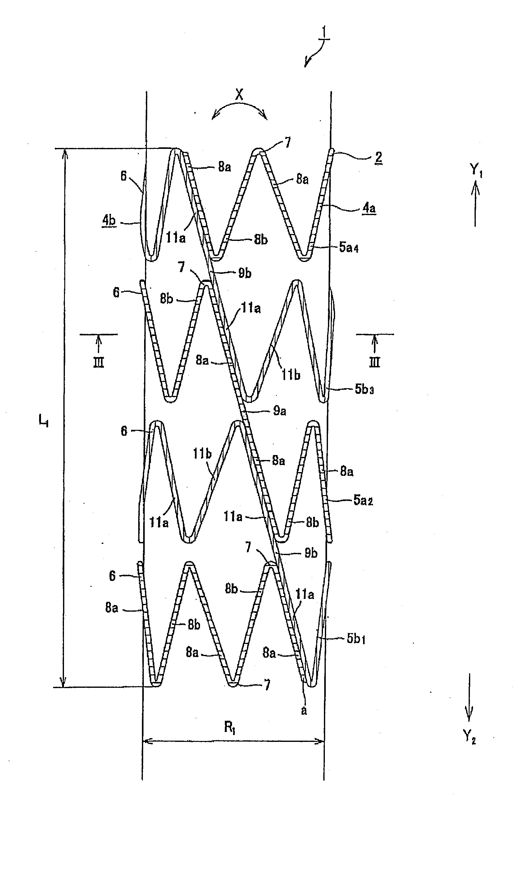
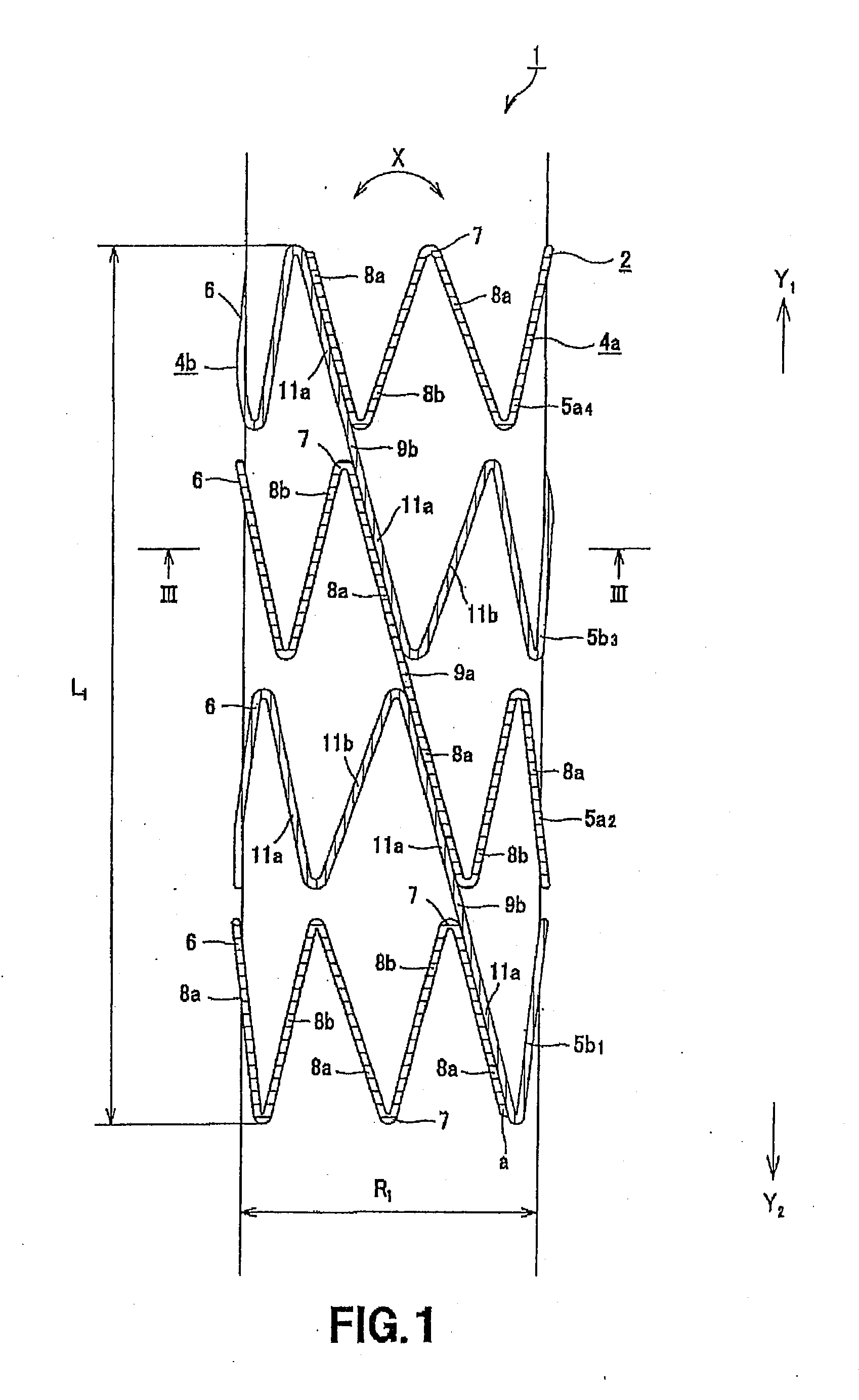
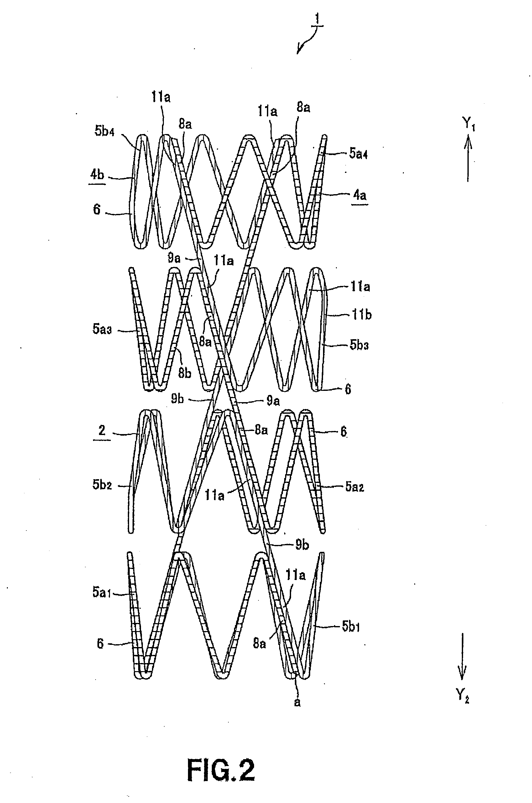
[0047] A stent for a vessel 1 according to the present invention is used as it is implanted in a blood vessel, such as a coronary artery of a living body, and is comprised with tubular body 2 of cylindrical shape, as shown in FIGS. 1 to 3.

[0048]FIG. 1 is a side view showing one-way semi-cylindrical part of the tubular body 2 formed cylindrically. FIG. 2 is a perspective view of the entire tubular body 2 and FIG. 3 is a cross-sectional view taken along line III-III of FIG. 1.

[0049] The stent for a vessel 1 implanted in the blood vessel is made with outer diameter R1 of 3 to 5 mm and length L1 of 10 to 15 mm. This size is the one when the stent is implanted in the blood vessel of the living body.

[0050] Meanwhile, the size of the stent for a vessel 1 is selected as appropriate depending on the vessel in which the stent is implanted.

[0051] The...


PUM

PropertyMeasurementUnit
Angleaaaaaaaaaa
Angleaaaaaaaaaa
Angleaaaaaaaaaa

Abstract

Disclosed is a stent for a vessel implanted and left in the vessel of a living body to support the lumen of the vessel from inside. The stent for a vessel consists of a plurality of stent constituting members (4a and 4b), formed by combining a plurality of the tubular-body constituting elements (5a and 5b) in multistage, each of the tubular-body forming elements (5) comprising a part of a tubular member (2) is formed by bending a yarn (3) of a biodegradable polymer in a zigzag design. Each of stent constituting members (4a and 4b) is comprised with tubular segments (6) formed by combining the tubular-body forming elements (5a and 5b) facing each other, and by continuously joining at least neighboring parts of each tubular-body forming element (5a and 5b) together, to comprise a continuously joined tubular body (2).

Description

TECHNICAL FIELD [0001] This invention relates to a stent for a vessel implanted in a vessel of a living body, such as blood vessel, trachea or biliary, to support the lumen of the vessel from inside. BACKGROUND ART [0002] Heretofore, if a stenosis has occurred in a vessel of a living body, in particular the blood vessel, such as artery, a balloon forming portion provided in the vicinity of the distal end of a balloon catheter is inserted into this stenosis portion, and the wrapped balloon forming portion is inflated to expand the stenosis portion of the blood vessel to improve the blood flow in the vessel. This operation is termed percutaneous transluminal angioplasty (PTA). [0003] However it has been known, if the PTA is applied, stenosis tends to be reproduced at a high probability in the once stenosis portion. [0004] To prevent this restenosis, the technique of implanting a tubular stent in the site applied PTA has been used. This stent is inserted into the blood vessel as it is ...

Claims


Application Information

Patent Timeline
IPC IPC(8): A61F2/82A61F2/90
CPCA61F2/88A61F2/90A61F2002/828A61F2250/006A61F2210/0004
Inventor IGAKI, KEIJI
Owner IGAKI IRYO SEKKEI
Why Eureka
Try Eureka