High ac current high RF power ac-RF decoupling filter for plasma reactor heated electrostatic chuck

a plasma reactor and electrostatic chuck technology, applied in the field of high ac current high rf power acrf decoupling filter for plasma reactor heated electrostatic chuck, can solve the problems of destroying and failing the filter, affecting the control of the plasma, and affecting the operation of the filter circui

Active Publication Date: 2007-12-13
APPLIED MATERIALS INC
View PDF9 Cites 86 Cited by
  • Summary
  • Abstract
  • Description
  • Claims
  • Application Information

AI Technical Summary

Problems solved by technology

The electric heater circuit therefore is a significant RF load on the ESC or cathode.
This diversion hampers control of the plasma because the plasma sheath voltage and ion energy (for example) are rendered uncertain and dependent upon the amount of capacitive coupling to the heater element, which may vary randomly.
At such a high RF voltage, the high frequency (13.56 MHz) oscillation in magnetic field in the core causes extreme heating of the high permeability magnetic core and, ultimately, destruction and failure of the filter.
We have found this problem in all of the commercially available RF filter

Method used


Image

  • High ac current high RF power ac-RF decoupling filter for plasma reactor heated electrostatic chuck
  • High ac current high RF power ac-RF decoupling filter for plasma reactor heated electrostatic chuck
  • High ac current high RF power ac-RF decoupling filter for plasma reactor heated electrostatic chuck

Examples


Embodiment Construction

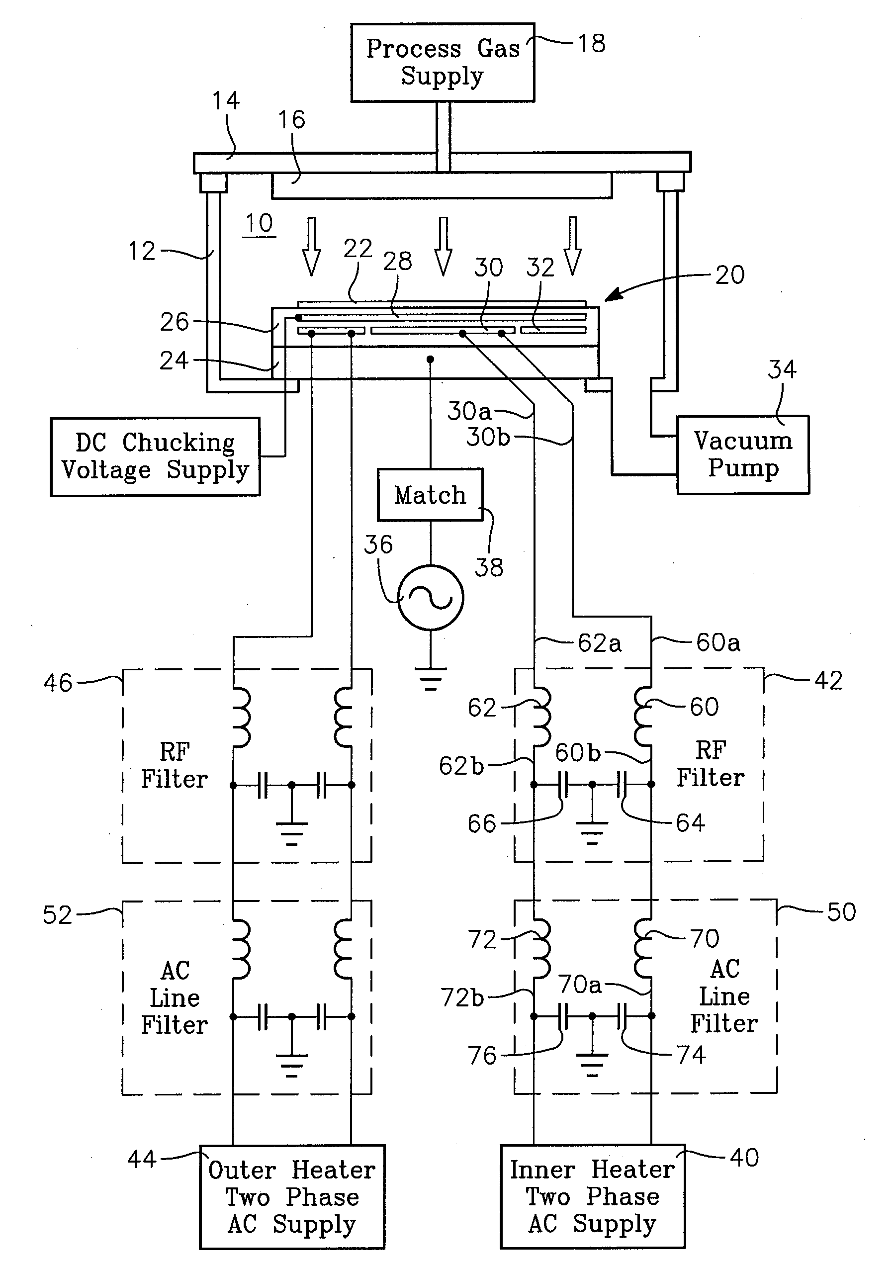
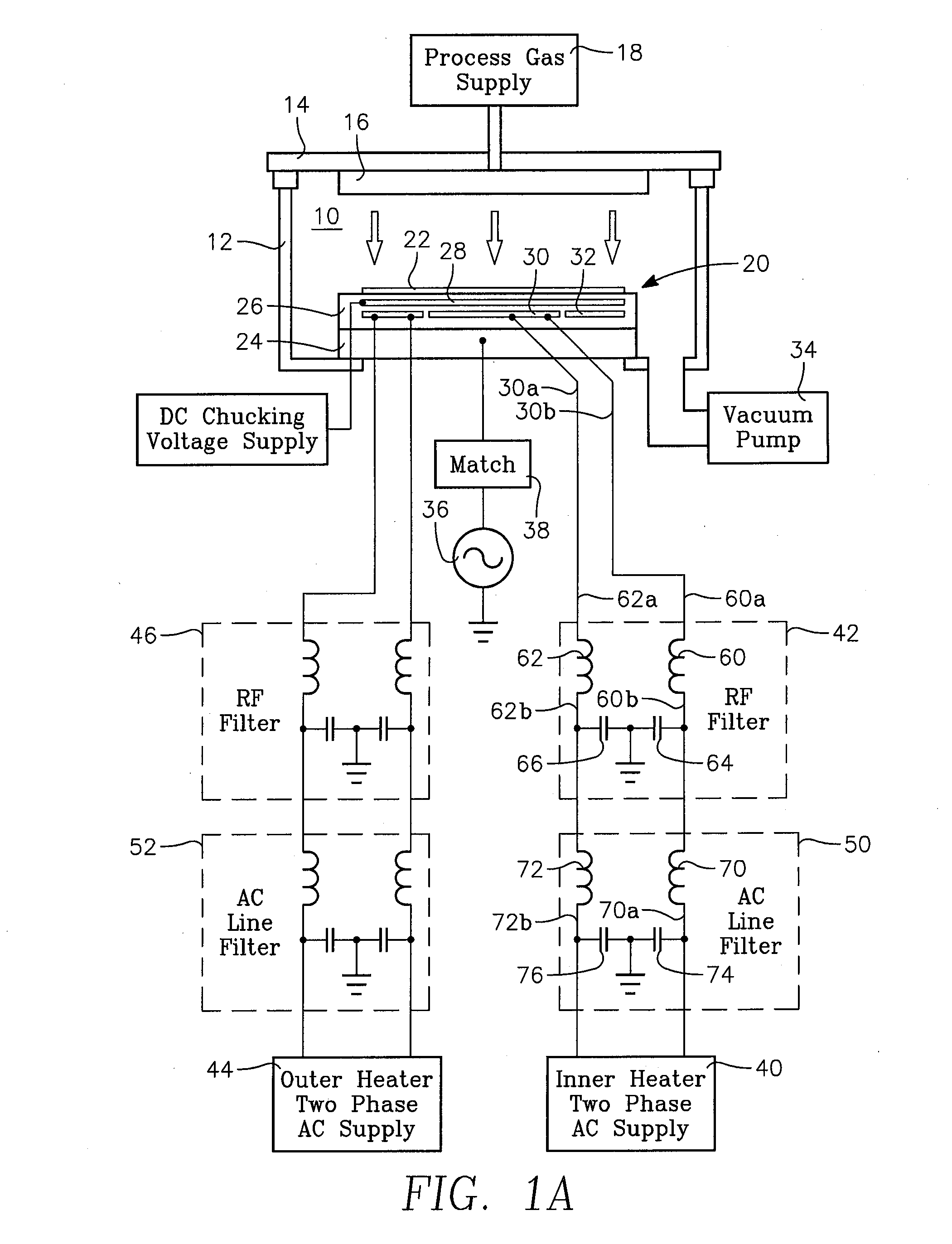
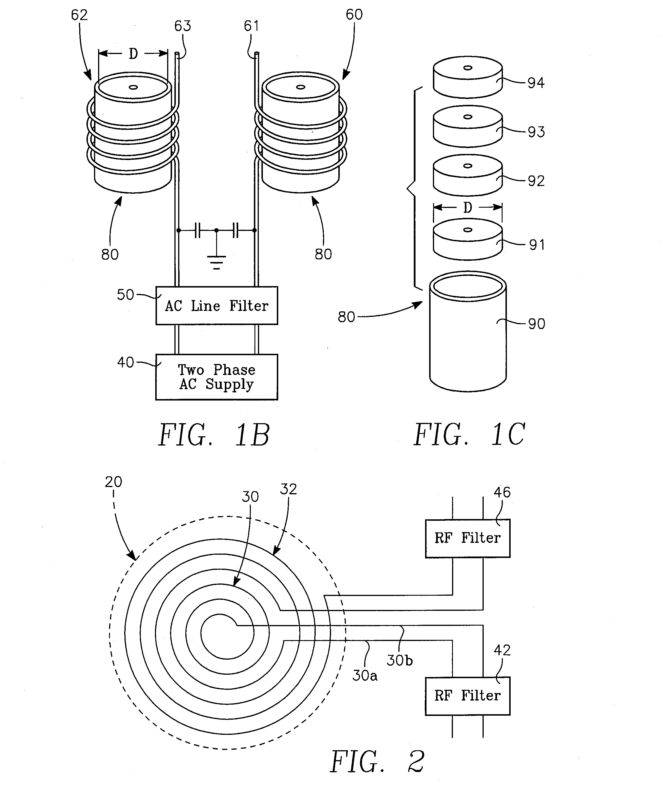
[0008]Referring to the apparatus of FIGS. 1A, 1B and 1C, a plasma reactor consists of a vacuum chamber 10 defined by a cylindrical side wall 12 supporting a ceiling 14 that includes a process gas distribution showerhead 16. A process gas supply 18 is coupled to the gas distribution showerhead. An electrostatic chuck (ESC) 20 holds a semiconductor wafer 22 in the chamber 10. The ESC 20 consists of a conductive base 24 and an insulating layer 26 that may be formed of a ceramic material. A chucking electrode 28 consisting of a conductive mesh is contained within the insulating layer 26. Inner and outer spiral heating elements 30, 32 (FIG. 2) are held within the insulating layer 26 beneath the chucking electrode 28. A vacuum pump 34 maintains a sub-atmospheric pressure within the chamber 10.

[0009]An RF bias power supply 36 is coupled through an impedance match circuit 38 to either the conductive base 24 or the chucking electrode 28. The RF bias supply preferably has an HF or LF frequenc...


PUM

PropertyMeasurementUnit
Lengthaaaaaaaaaa
Lengthaaaaaaaaaa
Lengthaaaaaaaaaa

Abstract

An RF blocking filter isolates a two-phase AC power supply from at least 2 kV p-p of power of an HF frequency that is reactively coupled to a resistive heating element, while conducting several kW of 60 Hz AC power from the two-phase AC power supply to the resistive heating element without overheating, the two-phase AC power supply having a pair of terminals and the resistive heating element having a pair of terminals. The filter includes a pair of cylindrical non-conductive envelopes each having an interior diameter between about one and two inches and respective pluralities of fused iron powder toroids of magnetic permeability on the order of about 10 stacked coaxially within respective ones of the pair of cylindrical envelopes, the exterior diameter of the toroids being about the same as the interior diameter of each of the envelopes. A pair of wire conductors of diameter between 3 mm and 3.5 mm are helically wound around corresponding ones of the pair of envelopes to form respective inductor windings in the range of about 16 to 24 turns for each the envelope, each of the conductors having an input end and an output end. The input end of each one of the conductors is coupled to a corresponding one of the pair of terminals of the two-phase AC power supply, and the output end of each one of the conductors is coupled to a corresponding one of the pair of terminals of the resistive heating element.

Description

CROSS-REFERENCE TO RELATED APPLICATIONS[0001]This application claims the benefit of U.S. Provisional Application Ser. No. 60 / 813,572, filed Jun. 13, 2006.BACKGROUND OF THE INVENTION[0002]Plasma reactors employed in semiconductor integrated circuit fabrication can use an electrostatic chuck (ESC) for holding the wafer inside the reactor chamber. Process control is enhanced by regulating the temperature of the semiconductor wafer held on the ESC. For example, a typical plasma etch process for forming high aspect ratio openings in the surface of a silicon wafer is carried out by introducing a process gas such as a fluorocarbon or fluorohydrocarbon gas into the chamber and coupling RF power into the chamber. Plasma RF source power for controlling plasma ion density may be applied by coupling VHF power to a ceiling electrode. Plasma RF bias power for controlling the plasma sheath voltage may be applied by coupling HF power to the ESC. In order to control the wafer temperature, an electri...

Claims


Application Information

Patent Timeline
IPC IPC(8): B23K9/00
CPCH01J37/32706H05H1/46H03H1/0007
Inventor TODOROV, VALENTIN N.WILLWERTH, MICHAEL D.PATERSON, ALEXANDERHATCHER, BRIAN K.SAMMONS, JAMES E.HOLLAND, JOHN P.
Owner APPLIED MATERIALS INC
Why Eureka
Try Eureka