Hybrid Multi-Tiered Caching Storage System

Active Publication Date: 2007-12-13
BITMICRO LLC
View PDF15 Cites 241 Cited by
  • Summary
  • Abstract
  • Description
  • Claims
  • Application Information

AI Technical Summary

Benefits of technology

[0006] A hybrid storage system comprising mechanical disk drive means, flash memory means, SDRAM memory means, and SRAM memory means for data storage is described. IO processor means and multiple DMA controller means are dev

Problems solved by technology

However, the translation from logical address to physical address format suitable for acce

Method used


Image

  • Hybrid Multi-Tiered Caching Storage System
  • Hybrid Multi-Tiered Caching Storage System
  • Hybrid Multi-Tiered Caching Storage System

Examples


Example

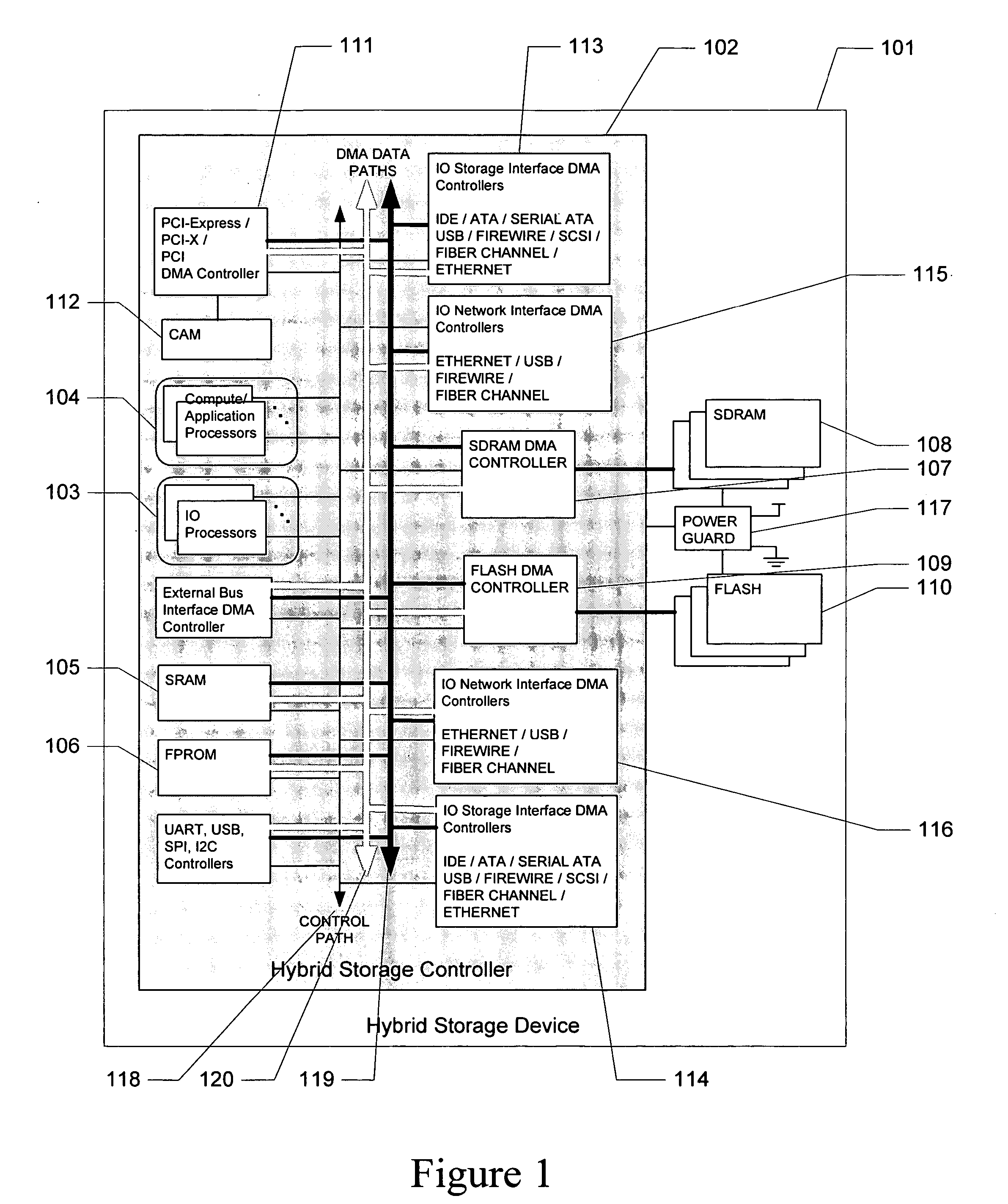
[0039]FIG. 1 is a diagram illustrating the components comprising the hybrid storage device 101 according to an embodiment of the present invention.

[0040] The hybrid storage device 101 comprises several storage devices listed as follows in order of increasing storage capacity and decreasing access time—embedded SRAM 105, array of SDRAM devices 108, array of flash devices 110 and array of hard drives (not shown). Three levels of caching are implemented in the storage system: flash array caches data in hard drives, SDRAM array caches data in flash array, SRAM caches data in SDRAM array. The main non-volatile storage component comprises one or more hard disks (not shown).

[0041] Hybrid storage controller 102 is a chip that manages the storage system. It contains multiple embedded DMA controllers:

[0042] PCI-Express / PCI-X / PCI DMA controller 111 handles byte or word addressable access to stored data by any device connected via a system bus such as: PCI-Express, PCI-X, PCI interface. Cont...


PUM


Abstract

A hybrid storage system comprising mechanical disk drive means, flash memory means, SDRAM memory means, and SRAM memory means is described. IO processor means and DMA controller means are devised to eliminate host intervention. Multi-tiered caching system and novel data structure for mapping logical address to physical address results in a configurable and scalable high performance computer data storage solution.

Description

BACKGROUND [0001] 1. Field [0002] The present invention relates to a data storage system which is applied to a computer system, and comprises volatile (e.g. SRAM, SDRAM) and nonvolatile (e.g. flash memory, mechanical hard disk) storage components. [0003] 2. Description of Related Art [0004] In a conventional computer system, a hard disk drive (HDD) is used as an external memory device wherein a magnetic disk is used as a storage medium. The HDD can be used as a large-capacity file apparatus. However, as compared to a main memory comprising a semiconductor memory (e.g. a DRAM), the access speed of the HDD is lower. A cache system for the HDD has been known as means for increasing the access speed of the HDD. Dynamic random access memory (DRAM) and flash memory has been used to implement a cache system for the HDD. However, the translation from logical address to physical address format suitable for accessing flash memory and HDD consume resources of the host computer and affects perf...

Claims


Application Information

Patent Timeline
IPC IPC(8): G06F12/00G06F13/00
CPCG06F3/061G06F3/064G06F3/0685G06F12/0897G06F13/28G06F2212/2022G06F2212/217G06F12/0866
Inventor BRUCE, REYMATEO, NOEME PAZNITE, RICKY SEVILLA
Owner BITMICRO LLC
Why Eureka
Try Eureka