Exhaust gas aftertreatment device for an internal combustion engine

Active Publication Date: 2007-12-20
PUREM GMBH
View PDF13 Cites 38 Cited by
  • Summary
  • Abstract
  • Description
  • Claims
  • Application Information

AI Technical Summary

Benefits of technology

[0004] The invention is based on the general idea of repeatedly deflecting a stream of exhaust gas to be cleaned in the exhaust gas after-treatment device and thereby achieving an especially good and thorough mixing of the exhaust gas with the added urea. The exhaust gas after-treatment device includes a housing with a pipe opening into a mixing chamber and penetrating into the housing. The mixing chamber is pot-shaped and inverted over the mouth of the exhaust pipe so that the direction of flow of the incoming exhaust gas is reversed and the exhaust is deflected back radially outside of the exhaust pipe. An open end of the pot-shaped mixing chamber opens into a collecting space preferably designed to be airtight and can therefore supply the exhaust wi

Problems solved by technology

The disadvantage of the previous method is in particular the fact that mixi

Method used


Image

  • Exhaust gas aftertreatment device for an internal combustion engine
  • Exhaust gas aftertreatment device for an internal combustion engine
  • Exhaust gas aftertreatment device for an internal combustion engine

Examples


Example

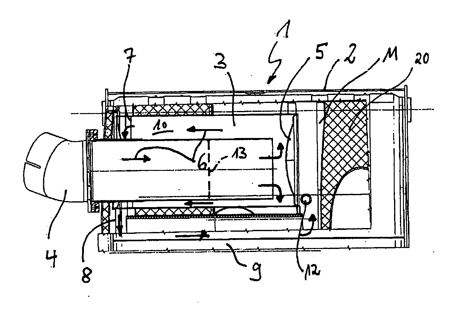
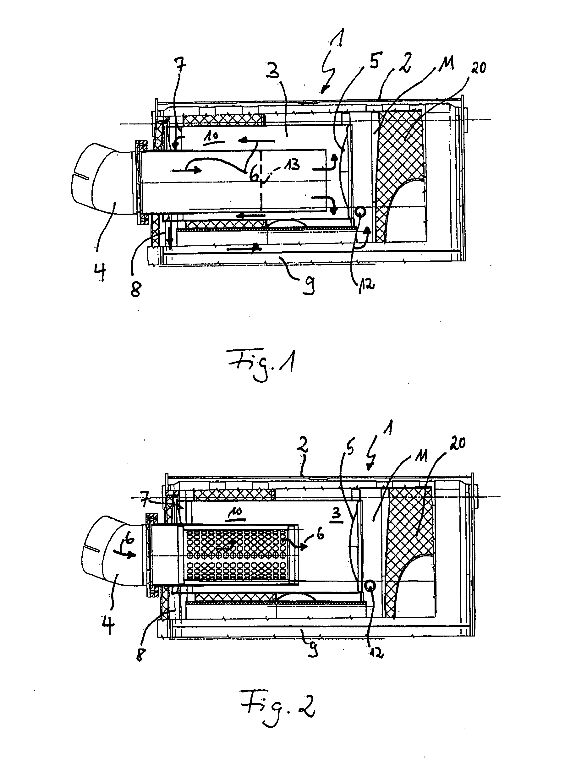
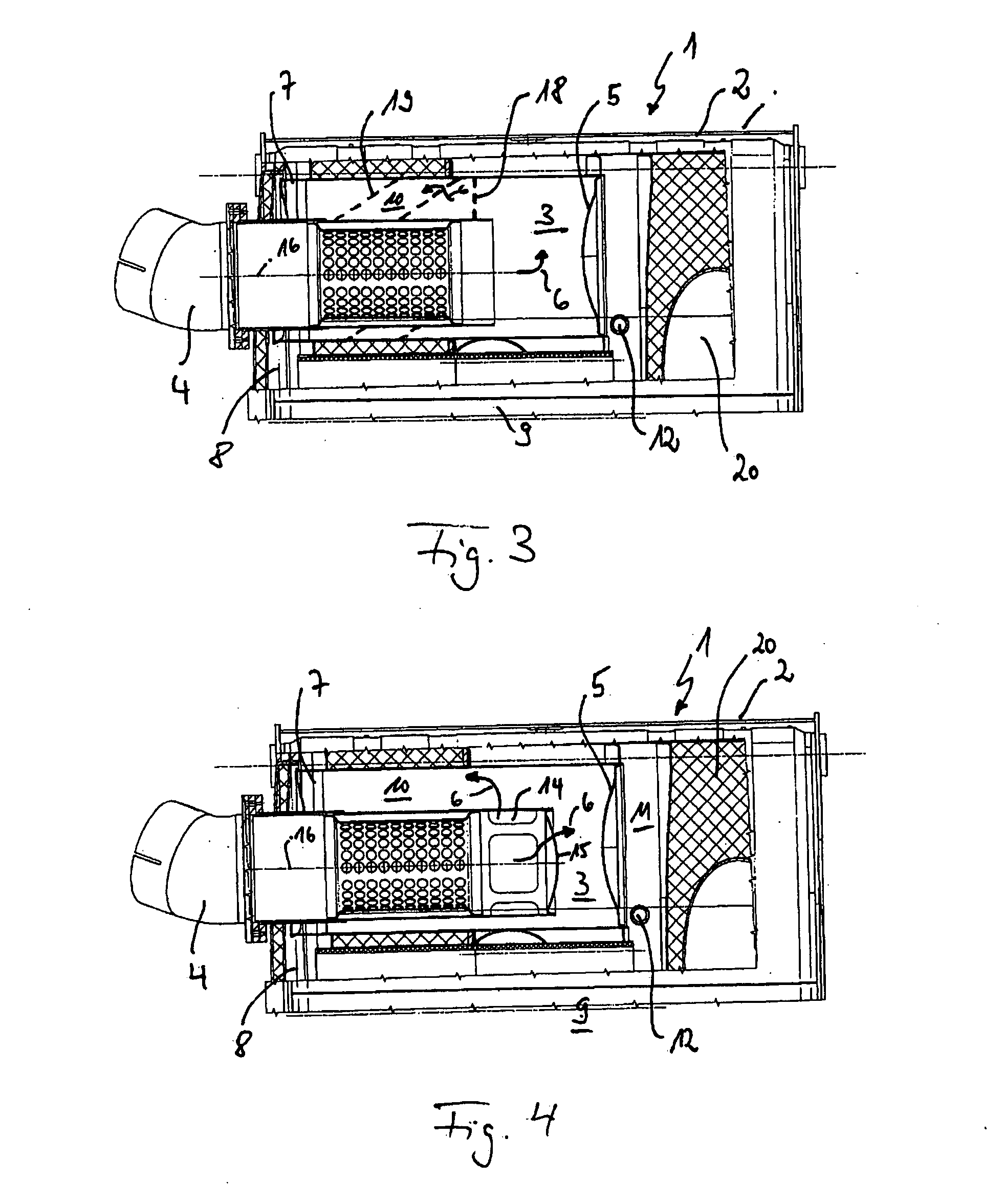
[0021] According to FIG. 1, an exhaust gas after-treatment device 1 for an internal combustion engine (not shown) has a housing 2 into which penetrates an exhaust pipe 4 that opens into a mixing chamber 3. The mixing chamber 3 is designed in the form of a pot and has a curved baffle plate 5 in all embodiments. This baffle plate 5 may have a sintered metal plate, for example or may be designed as such. The mixing chamber 3 serves to thoroughly mix the exhaust gas which is flowing into the exhaust gas after-treatment device 1 and to which a reducing agent such as urea has previously been added. For successful removal of the nitrogen oxides present in the exhaust gas, the exhaust gas must preferably be mixed homogeneously with the reducing agent, e.g., the urea. As shown in FIG. 1, the exhaust gas flows from left to right through the exhaust pipe 4 into the mixing chamber 3 along the flow arrows 6. The pot-shaped design of the mixing chamber 3 causes the inflowing exhaust to undergo a ...


PUM


Abstract

The invention relates to an exhaust gas after-treatment device for an internal combustion engine, including a housing into which an exhaust pipe that opens into a mixing chamber penetrates. The mixing chamber is shaped as a pot and reverses a direction of flow of the incoming exhaust gas whereby it returns the exhaust gas radially outside of the exhaust pipe. An open end of the pot-shaped mixing chamber opens into a collecting space which is designed so that it supplies the exhaust gas to at least one downstream SCR catalytic converter.

Description

FIELD OF THE INVENTION [0001] The present invention relates to an exhaust gas after-treatment device for an internal combustion engine. BACKGROUND OF THE INVENTION [0002] A selective catalytic reduction method (SCR method) refers to a selective chemical reaction in which only the nitrogen oxides are reduced instead of all the exhaust gas components of the exhaust. In automotive engineering, this method is increasingly being used in trucks and commercial vehicles having diesel engines to make it possible to reduce pollutant emissions to the extent that they comply with the EU4 standard. The ammonia required for the reduction is not added directly, i.e., in pure form, but instead is added in the form of an aqueous urea solution which is injected into the exhaust line where it triggers cleavage of the urea-water solution into ammonia and water by means of a hydrolysis reaction. The advantage of the SCR method is the removal of soot particles and nitrogen oxides from the exhaust and the...

Claims


Application Information

Patent Timeline
IPC IPC(8): F01N3/10F01N13/00
CPCF01N1/084F01N13/0097F01N3/0335F01N3/035F01N3/2066F01N3/2803F01N3/2885F01N3/2892F01N2240/20F01N2470/02F01N2470/30F01N2560/026F01N2610/02Y02T10/24F01N13/017F01N1/10Y02A50/20Y02T10/12
Inventor WERNI, MARCUSWOERNER, SIEGFRIEDBUHMANN, RUDOLFLEHNEN, RAINER
Owner PUREM GMBH
Why Eureka
Try Eureka