
System and method for thermal management and gradient reduction

a technology of thermal management and gradient reduction, applied in the direction of electronic circuit testing, measurement devices, instruments, etc., can solve the problems of increasing ic failure, physical inability to mechanically probe chips, and need for fast and accurate chip probing, debugging and failure analysis technologies, etc., to reduce or prevent stagnation points over the dut, the effect of preventing stagnation at the intersection

Inactive Publication Date: 2007-12-20
DCG SYST
View PDF20 Cites 23 Cited by
  • Summary
  • Abstract
  • Description
  • Claims
  • Application Information

AI Technical Summary

Benefits of technology

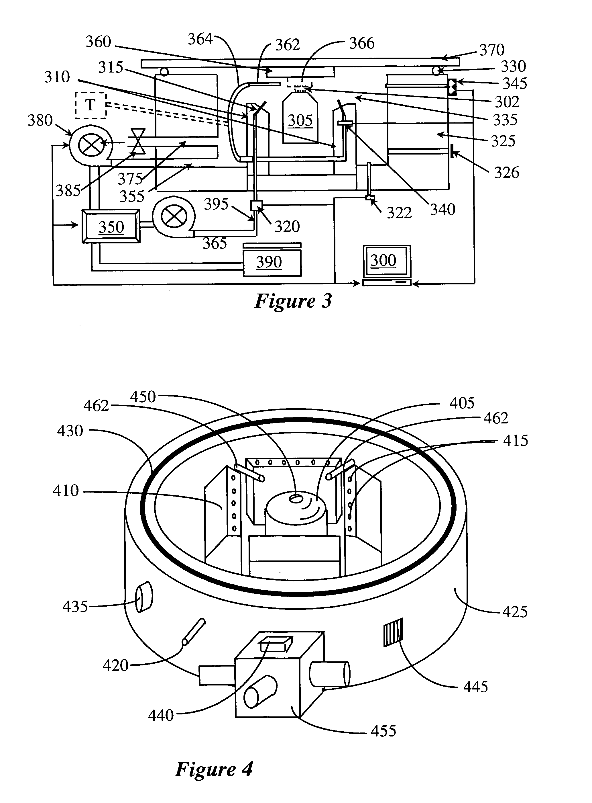
"The present invention provides a mechanism for removing heat from a DUT (device under test) using a thermal management system. This allows for inspection of the device under electrical stimulation. The system uses an atomized liquid spray for controlling the temperature of the DUT, and a flow inducing injector to prevent stagnation points. The spray is accomplished using several banks of atomizers or nozzles which provide fine spray, fine mist, or fine droplets. The spray chamber pressure and vapor temperature are monitored, and the spray flow inducing injector is provided to induce flow at the intersection of the atomizers' stream. The control instrumentation includes a controller that can control the fluid temperature, flow rate, spray pattern, and density, and an optional mechanical pressure relief valve. The invention also includes a solid immersion lens (SIL) for transmission of optical energy between the DUT and the objective lens regardless of the type and manner of cooling spray used. Multiple flow inducing injectors can be used simultaneously or individually to reduce stagnation at various locations."

Problems solved by technology

With increased IC production comes the possibility of increased IC failure, as well as the need for fast and accurate chip probing, debug, and failure analysis technologies.
Due to the extremely high circuit densities, speeds, and complexities of today's chips, including the use of flip-chip technology, it is now physically impossible to probe the chips mechanically without destructively disassembling them.
Such activity results in considerable heat generation.
However, when the device is under test, the device is not encapsulated and, typically, its substrate is thinned down for testing purposes.
Consequently, no means for heat dissipation are available and the device under test (DUT) may operate under excessive heat so as to distort the tests, and may ultimately fail prematurely.
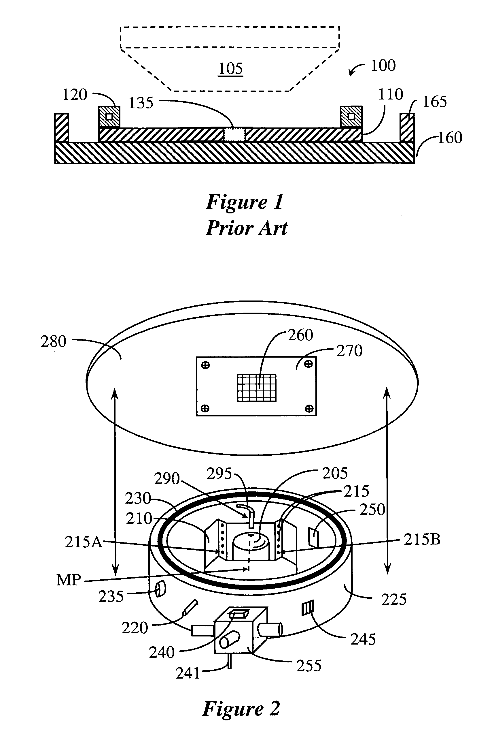
Typically, however, the DUT includes auxiliary devices 165, which limit the available motion of the cooling plate, thereby limiting the area available for probing To overcome this, custom plates are made for specific devices, leading to increased cost and complexity of operation of the tester.

Method used


Image

  • System and method for thermal management and gradient reduction
  • System and method for thermal management and gradient reduction
  • System and method for thermal management and gradient reduction

Examples


Embodiment Construction

[0028]Various embodiments and implementations of the present invention can be used in conjunction with various IC testers and probers, so as to provide cooling of an IC that is electrically stimulated. In one general aspect, an atomized liquid spray is provided about a probe head so as to cool the DUT as the probe head collects data. Any probe head may be used, for example, the probe head may be in the form of an optical photon-counting time-resolved receiver, optical emission microscope, or laser-based probing tool. In order to provide a more detailed explanation of various aspects and features of the invention, the invention will be described with reference to more specific IC probers, i.e., optical photon-counting time-resolved emission probers. However, it should be appreciated that such detailed description is provided only as an example and not by way of limitation.

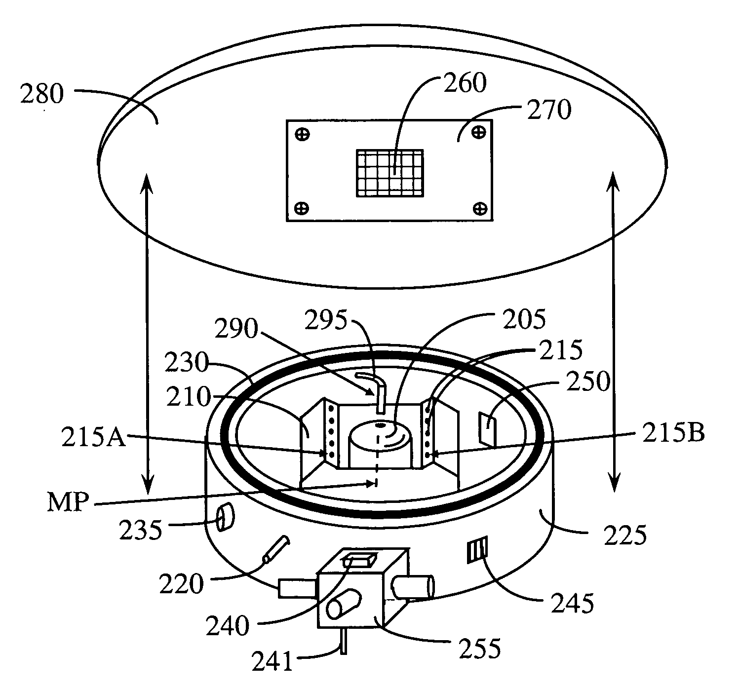
[0029]FIG. 2 depicts an exploded view of one embodiment of the inventive cooling system. The cooling system depic...


PUM


Abstract

A micro-spray cooling system beneficial for use in testers of electrically stimulated integrated circuit chips is disclosed. The system includes micro-spray heads disposed about a probe head, which provide a coolant flow onto the IC. A flow inducing injector is provided that directs a fluid jet onto zones where stagnation of the coolant flow is present. This reduces or eliminates any stagnation points and enhance temperature uniformity over the area of the IC.

Description

BACKGROUND OF THE INVENTION[0001]1. Field of the Invention[0002]The present invention relates to a system and a method for thermal management of an electrically stimulated semiconductor integrated circuit undergoing probing, diagnostics, or failure analysis.[0003]2. Description of the Related Art[0004]Integrated circuits (ICs) are being used in increasing numbers of consumer devices, apart from the well-known personal computer itself. Examples include automobiles, communication devices, and smart homes (dishwashers, furnaces, refrigerators, etc.). This widespread adoption has also resulted in ever larger numbers of ICs being manufactured each year. With increased IC production comes the possibility of increased IC failure, as well as the need for fast and accurate chip probing, debug, and failure analysis technologies. The primary purpose of today's probing, debug, and failure analysis systems is to characterize the gate-level performance of the chip under evaluation, and to identif...

Claims


Application Information

Patent Timeline
Patent Type & Authority Applications(United States)
IPC IPC(8): G01R31/02
CPCG01R31/311
Inventor LEE, BIRK
Owner DCG SYST
Learn More