Liquefied Natural Gas Processing

Active Publication Date: 2008-01-03
UOP LLC
View PDF99 Cites 91 Cited by
  • Summary
  • Abstract
  • Description
  • Claims
  • Application Information

AI Technical Summary

Problems solved by technology

Although there are many processes which may be used to separate ethane and heavier hydrocarbons from LNG, these processes often must compromise between high recovery, low utility costs, and process simplicity (and hence low capital investment).
However, lower utility costs

Method used


Image

  • Liquefied Natural Gas Processing
  • Liquefied Natural Gas Processing
  • Liquefied Natural Gas Processing

Examples


example 1

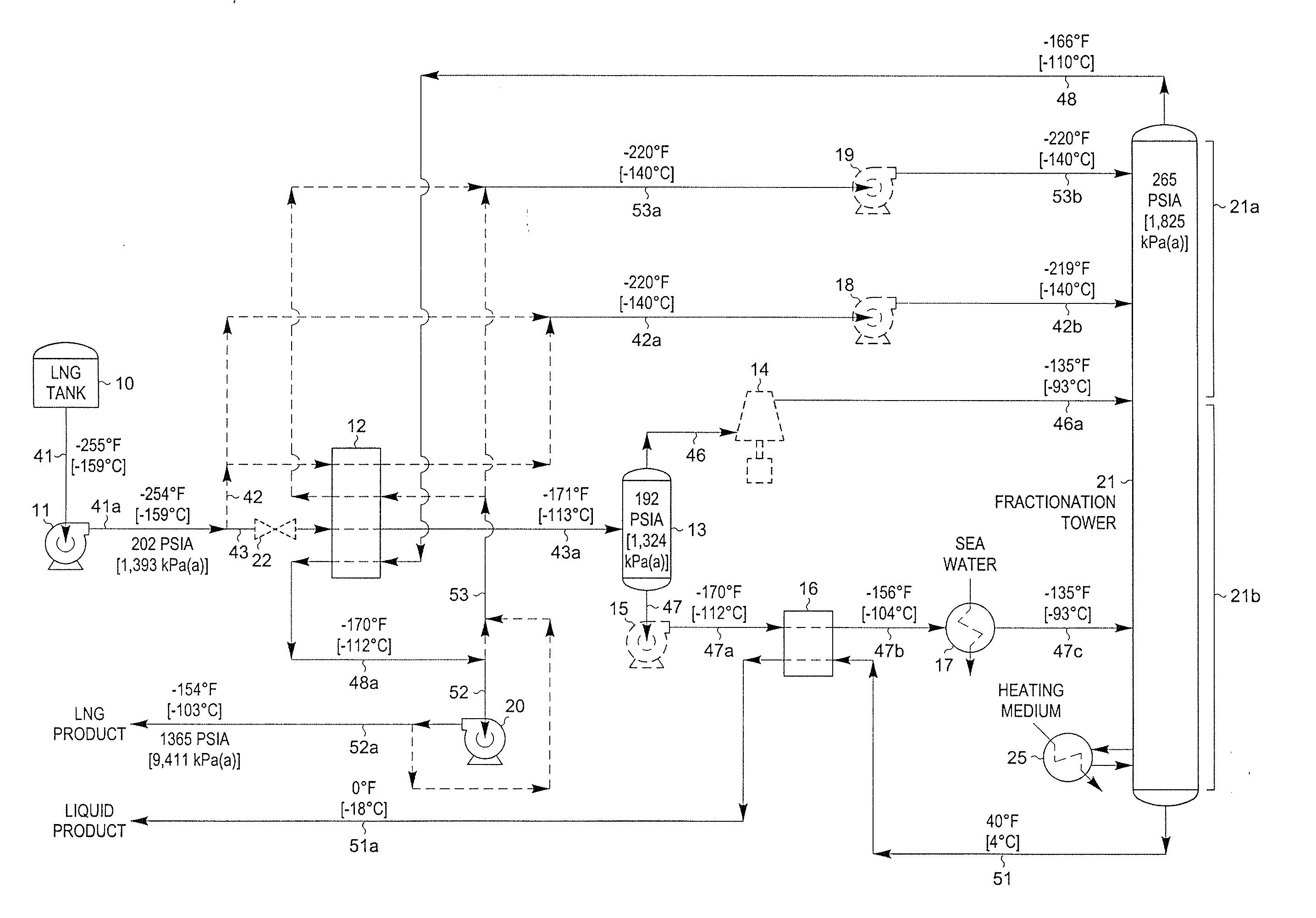
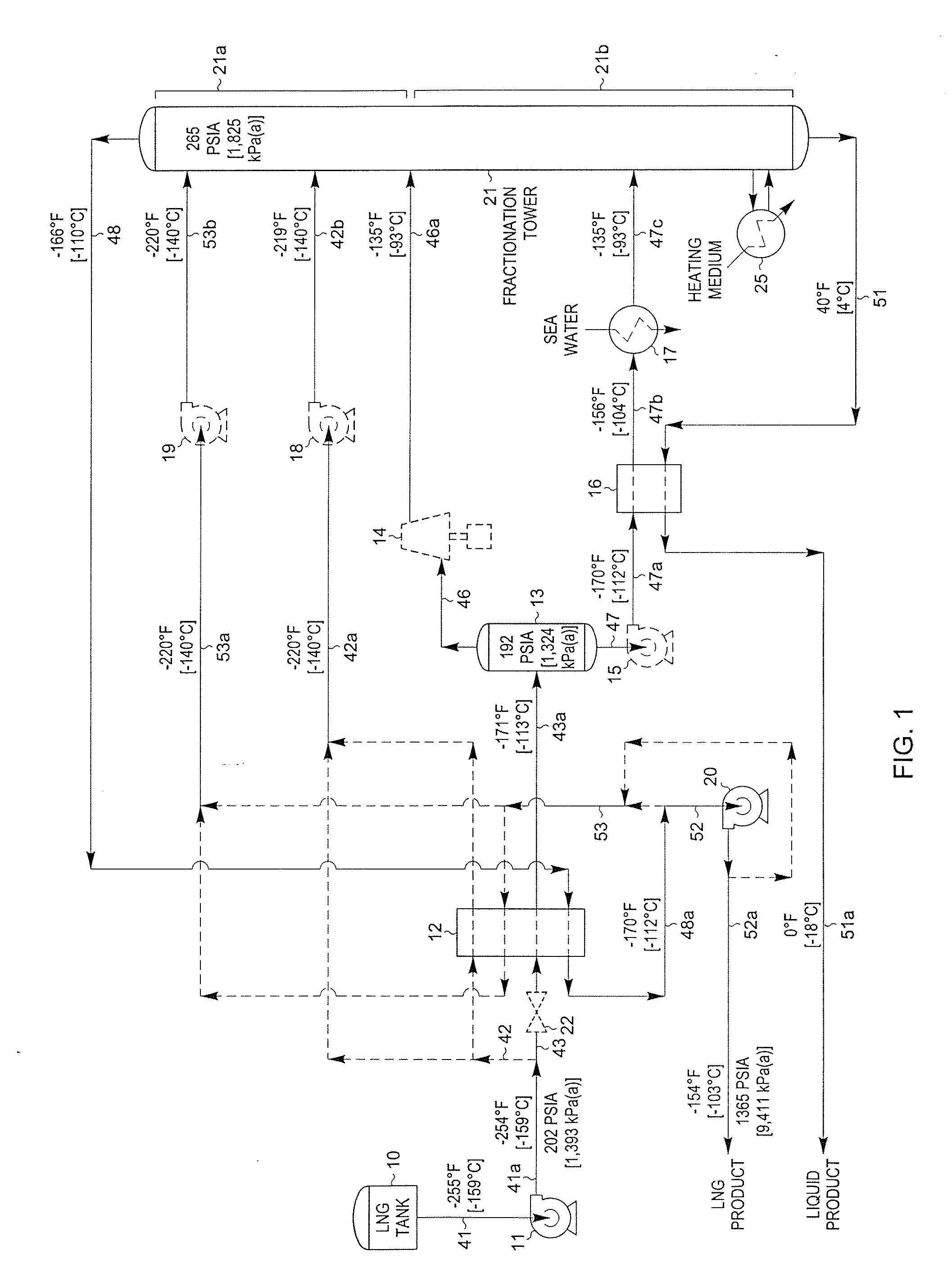
[0011]FIG. 1 illustrates a flow diagram of a process in accordance with the present invention adapted to produce an NGL product containing the majority of the C2 components and heavier hydrocarbon components present in the feed stream.

[0012] In the simulation of the FIG. 1 process, the LNG to be processed (stream 41) from LNG tank 10 enters pump 11 at −255° F. [−159° C.], which elevates the pressure of the LNG sufficiently so that it can flow through heat exchangers and thence to separator 13. Stream 41a exiting the pump is split into two portions, streams 42 and 43. The first portion, stream 42, is heated to −220° F. [−140° C.] (stream 42a) in heat exchanger 12 and then is pumped to higher pressure by pump 18. Pumped stream 42b at −219° F. [−140° C.] is then supplied to fractionation column 21 at an upper mid-column feed point.

[0013] The second portion of stream 41a (stream 43) is heated prior to entering separator 13 so that at least a portion of it is vaporized. In the example ...

example 2

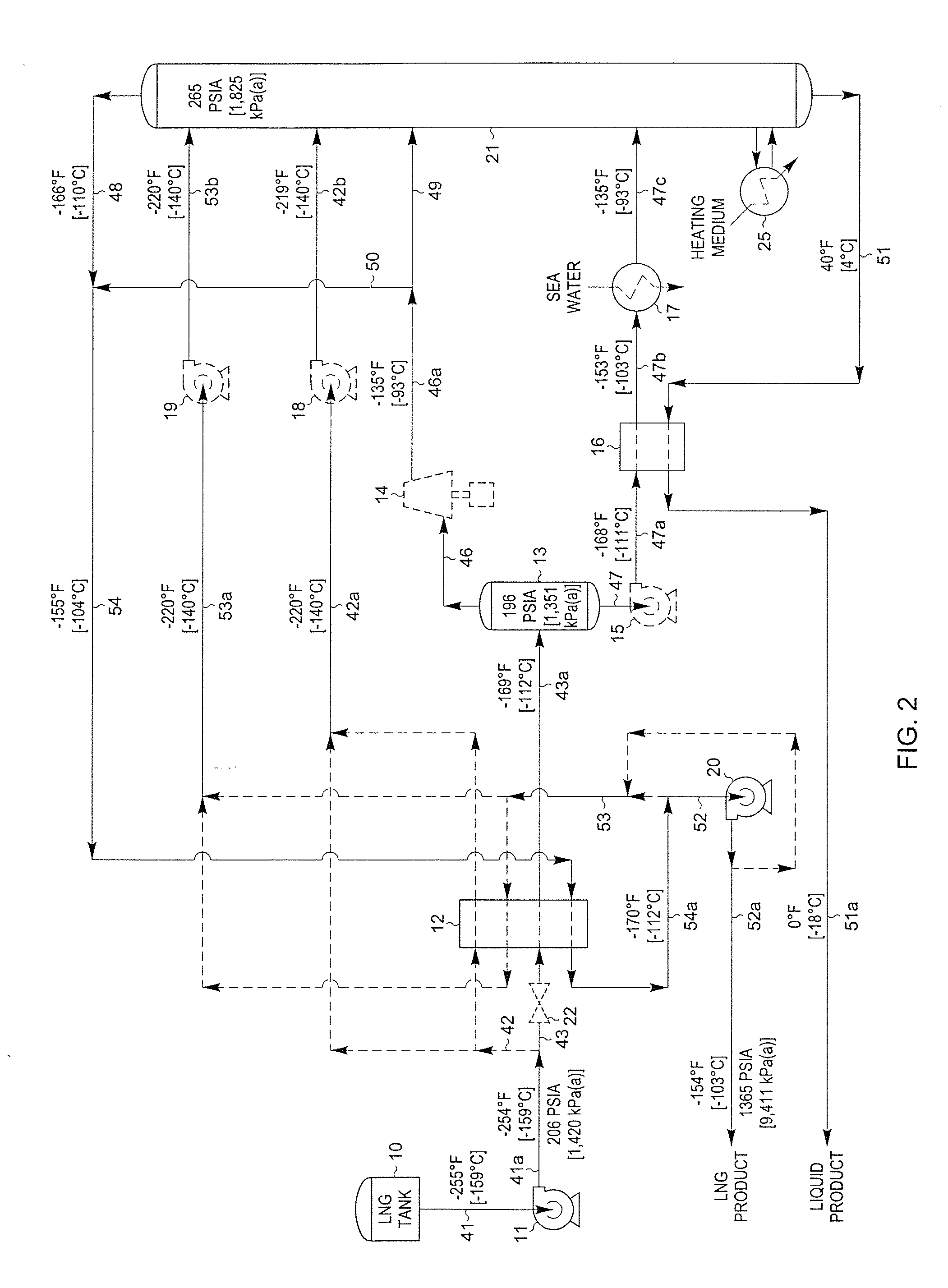
[0021] An alternative embodiment of the present invention is shown in FIG. 2. The LNG composition and conditions considered in the process presented in FIG. 2 are the same as those in FIG. 1. Accordingly, the FIG. 2 process of the present invention can be compared to the embodiment displayed in FIG. 1.

[0022] In the simulation of the FIG. 2 process, the LNG to be processed (stream 41) from LNG tank 10 enters pump 11 at −255° F. [−159° C.]. Pump 11 elevates the pressure of the LNG sufficiently so that it can flow through heat exchangers and thence to separator 13. Stream 41a exiting the pump is split into two portions, streams 42 and 43. The first portion, stream 42, is heated to −220° F. [−140° C.] (stream 42a) in heat exchanger 12 and then is pumped to higher pressure by pump 18. Pumped stream 42b at −219° F. [−140° C.] is then supplied to fractionation column 21 at an upper mid-column feed point.

[0023] The second portion of stream 41 a (stream 43) is heated prior to entering sepa...

example 3

[0029] Another alternative embodiment of the present invention is shown in FIG. 3. The LNG composition and conditions considered in the process presented in FIG. 3 are the same as those in FIGS. 1 and 2. Accordingly, the FIG. 3 process of the present invention can be compared to the embodiments displayed in FIGS. 1 and 2.

[0030] In the simulation of the FIG. 3 process, the LNG to be processed (stream 41) from LNG tank 10 enters pump 11 at −255° F. [−159° C.]. Pump 11 elevates the pressure of the LNG sufficiently so that it can flow through heat exchangers and thence to separator 13. Stream 41a exiting the pump is split into two portions, streams 42 and 43. The first portion, stream 42, is heated to −220° F. [−140° C.] (stream 42a) in heat exchanger 12 and then is pumped to higher pressure by pump 18. Pumped stream 42b at −219° F. [−140° C.] is then supplied to fractionation column 21 at an upper mid-column feed point.

[0031] The second portion of stream 41a (stream 43) is heated pri...


PUM


Abstract

A process and apparatus for the recovery of ethane, ethylene, propane, propylene, and heavier hydrocarbons from a liquefied natural gas (LNG) stream is disclosed. The LNG feed stream is divided into two portions. The first portion is supplied to a fractionation column at an upper mid-column feed point. The second portion is directed in heat exchange relation with a warmer distillation stream rising from the fractionation stages of the column, whereby this portion of the LNG feed stream is partially vaporized and the distillation stream is totally condensed. The condensed distillation stream is divided into a “lean” LNG product stream and a reflux stream, whereupon the reflux stream is supplied to the column at a top column feed position. The partially vaporized portion of the LNG feed stream is separated into vapor and liquid streams which are thereafter supplied to the column at lower mid-column feed positions. The quantities and temperatures of the feeds to the column are effective to maintain the column overhead temperature at a temperature whereby the major portion of the desired components is recovered in the bottom liquid product from the column.

Description

CROSS REFERENCE TO RELATED APPLICATIONS [0001] The applicants claim the benefits under Title 35, United States Code, Section 119(e) of prior U.S. Provisional Application No. 60 / 810,244 which was filed on Jun. 2, 2006 and 60 / 812,686 which was filed on Jun. 8, 2006.BACKGROUND OF THE INVENTION [0002] This invention relates to a process for the separation of ethane and heavier hydrocarbons or propane and heavier hydrocarbons from liquefied natural gas, hereinafter referred to as LNG, to provide a volatile methane-rich lean LNG stream and a less volatile natural gas liquids (NGL) or liquefied petroleum gas (LPG) stream. [0003] As an alternative to transportation in pipelines, natural gas at remote locations is sometimes liquefied and transported in special LNG tankers to appropriate LNG receiving and storage terminals. The LNG can then be re-vaporized and used as a gaseous fuel in the same fashion as natural gas. Although LNG usually has a major proportion of methane, i.e., methane compr...

Claims


Application Information

Patent Timeline
IPC IPC(8): F17C9/04
CPCF25J3/0214F25J3/0233F25J3/0238F25J2200/02F25J2200/76F25J2240/02F25J2210/06F25J2230/08F25J2230/60F25J2235/60F25J2205/04H04W28/10F25J3/00
Inventor CUELLAR, KYLE T.WILKINSON, JOHN D.HUDSON, HANK M.
Owner UOP LLC
Why Eureka
Try Eureka