Parameter compaction in tile based rendering device

a tile-based rendering and parameter compaction technology, applied in the field of 3d computer graphics systems, can solve the problems of requiring memory allocation, the entire memory used by a scene cannot be freed until, etc., and achieve the effect of improving the amount of memory freed, reducing the probability of a memory block successfully being freed by a parameter compaction pass, and consuming a large quantity of memory

Active Publication Date: 2008-01-10
IMAGINATION TECH LTD
View PDF6 Cites 24 Cited by
  • Summary
  • Abstract
  • Description
  • Claims
  • Application Information

AI Technical Summary

Benefits of technology

[0015] Given that objects that update the stencil buffer can cause a relatively large number of objects to be retained it may be preferable to store the stencil buffer state itself. This allows the objects that update the stencil buffer image to be discarded and avoids the need to flush other valid objects at this time. The stencil buffer image needs to be saved at the point any object updates either depth or tag buffers. Based on its state, the memory for the saved stencil image is allocated using the same parameter memory management mechanism as is used for parameters. The same mechanism could be applied to depth only update objects, however these tend to be much fewer in number than stencil update objects and so do not tend to consume a large quantity of memory.
[0016] This mechanism can be combined with macro ti

Problems solved by technology

The presence of the screen space geometry lists imposes an overhead on tile based rendering systems (TBR) that is not required in conventional immediate mode rendering (IMR) architectures.
This method has the disadvantage of requiring memory to be allocated for a full size

Method used


Image

  • Parameter compaction in tile based rendering device
  • Parameter compaction in tile based rendering device
  • Parameter compaction in tile based rendering device

Examples


Embodiment Construction

[0028] It should be noted that the described embodiment makes the following assumptions about the manner in which memory is managed, [0029] Memory for object. pointers is allocated from separate memory blocks to object data. [0030] Pointer memory blocks are allocated per tile as apposed to per macro tile.

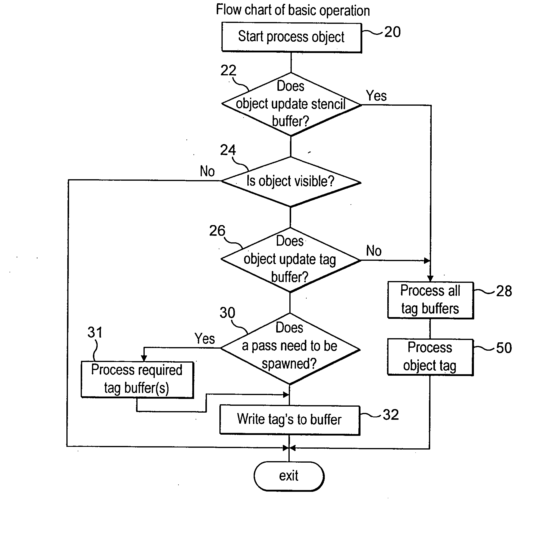
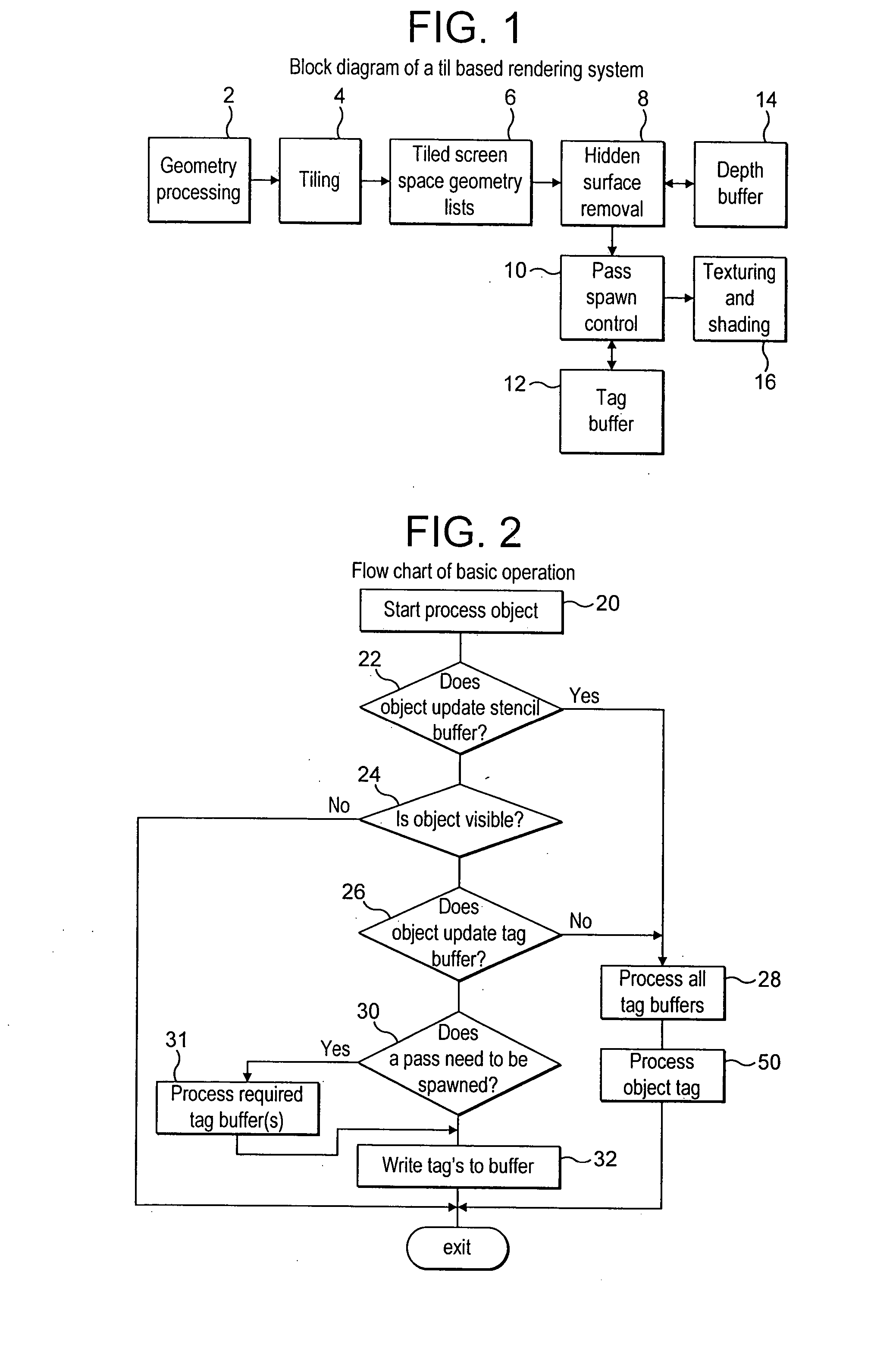
[0031]FIG. 2 illustrates the basic algorithm used to determine if an object is required and when the tag buffer should be processed. At 22 a determination is made as whether or not the object updates the stencil buffer, if it does, based on rule 3 above, then all tag buffers are processed at 28 and the object itself is processed at 50 before exiting.

[0032] If the object does not update the stencil buffer then the visibility of the object is determined at 24, if the object is not visible the algorithm exits. If the object is visible then it is determined at 26 if the object updates the tag buffer, if it does not then, in accordance with rule 4 above all tag buffers are processed at...


PUM


Abstract

A method and apparatus for managing memory usage for three-dimensional computer graphics systems are provided. A scene which is textured and shaded in the system is divided into a plurality of rectangular areas , each comprising a plurality of picture elements in the scene. For each rectangular area a list of objects which may be visible in the scene is derived. Objects which do not contribute to the final textured and shaded scene are then removed from each list and the rectangular area is then textured and shaded using reduced lists of objects.

Description

[0001] This invention relates to a 3-dimensional computer graphics system and in particular to methods and apparatus that reduce the amount of intermediate data stored in a tile based rendering system. [0002] Tile based rendering systems are known. These break down an image to be rendered into a plurality of rectangular blocks or tiles. The way in which this is done and the subsequent texturing and shading performed is shown schematically in FIG. 1. This shows a geometry-processing unit 2 that receives the image data from an application and transforms it into screen space using a well-known method. The data is then supplied to a tiling unit 4, which inserts the screen space geometry into lists for a set of defined rectangular regions, or tiles, 6. Each list contains primitives that exist wholly or partially in a sub-region of a screen (i.e. a tile). A list exists for every tile on the screen, although it should be borne in mind that some lists may have no data in them. [0003] Data t...

Claims


Application Information

Patent Timeline
IPC IPC(8): G09G5/39G06T15/40
CPCG06T15/40G06T1/60
Inventor HOWSON, JOHN
Owner IMAGINATION TECH LTD
Why Eureka
Try Eureka