Method and apparatus for radiation encoding and analysis

a radiation encoding and analysis technology, applied in the direction of optical radiation measurement, fluorescence/phosphorescence, instruments, etc., can solve the problems of reducing the photometric accuracy of these instruments, reducing the spatial or spectral resolution of the analyzer, and increasing the cost of the analyzer, etc., to achieve compact fluorescence, improve the and improve the effect of spatial or spectral resolution

Inactive Publication Date: 2008-01-10
MUDLOGGING SYST
View PDF46 Cites 27 Cited by
  • Summary
  • Abstract
  • Description
  • Claims
  • Application Information

AI Technical Summary

Benefits of technology

[0008] This invention provides many advantages over the radiation analyzers described above. In some embodiments, the intensity of the incident radiation is modulated independent of the bandwidth and that the amplitude of the modulated signal is a smooth function or changes between three or more distinct levels of contrast as the modulator is rotated about an axis or otherwise reciprocated. One can implement a multi-channel orthogonal encoding scheme for arbitrary center wavelengths and bandwidths and arbitrary radial intensity distributions. In this manner, the center wavelengths and bandwidths of the encoded channels can be independently optimized for a specific application. The before mentioned optical encoding scheme is combined with imaging optics so that radiation from an extended source or collection of discrete samples can be imaged using a single detector. This allows one to control the modulation depth on a channel-by-channel basis independent of the bandwidth, a design strategy which may be useful for balancing signal levels in systems where one or more channels have a disproportionately large fraction of the total incident radiation. This allows one to group modulation channels into complementary pairs where the amplitude and phase of the resulting encoded component are determined by the relative portion of radiation incident on the two filters comprising the pair. In this manner, intensity differences, wavelength derivatives, and the radial position of the center of an intensity distribution can be measured directly. This allows one to use one or more complementary filter pairs in conjunction with an expected radiation component for calibration and alignment purposes. One may also use a dedicated light source and detector and a series of marks on the modulator to detect spindle wobble, vibrations or a misaligned modulator pattern on the modulator substrate for calibration and alignment purposes. One can also measure a plurality of response radiation components as a function of two or more excitation components substantially simultaneously, enabling a fast, compact fluorescence, Raman or photo-refractive excitation / response analyzer. It is possible to use modulation functions which are based on incomplete periods of the rotation of the modulator, which can be used to eliminate various hardware items, free up micro-processor resources, synchronize the movements of external mechanical devices, measure both the radial position and the intensity of an imaged radiation component, and increase the spatial or spectral resolution of the analyzer. Finally, one may measure a plurality of spectral components individually selected from a collection of radiation emitting samples substantially simultaneously using a one-dimensional hyper-spectral imaging optic and a single channel detector.
[0011] In the preferred embodiment of the spectrum and imaging analyzers described above, the two-dimensional spatial radiation modulator contains a series of timing marks and the analyzer has a number of optical switches which are triggered by the timing marks to establish the absolute angle of rotation for decoding purposes. Most preferably, the timing marks will also trigger the data acquisition (DAQ) from the detector and the decoding algorithm, which in turn, will substantially relax any stability requirements of the modulators rotational period. Preferably, the analyzer will have a dedicated radiation source and an analog detector which is partially interrupted by the timing marks and / or other marks located on the modulator or spindle to detect spindle wobble or a misaligned pattern on the modulator. More preferably, the signal generated by the analog detector are processed by the computer to provide the decoding algorithm and / or the analytical function with one or more calibration coefficients used to compensate for the undesired effects of spindle wobble or a misaligned pattern. Most preferably, the signal generated by the analog detector are processed by the computer to provide a control signal to position of one or more optical elements to keep the image or dispersed image centered on the modulator pattern.
[0012] In the preferred embodiment of the spectrum and imaging analyzers described above, the analyzers computer will include a transient-signal algorithm that will detect transients in the amplitudes of the encoded components which occur during a rotational period of the modulator. Preferably, the computer will analyze the transient signal to determine its harmonic content. More preferably, the harmonic content will be used by the decoding algorithm to compensate for transient-induced harmonic interference. Preferably, the transient-signal algorithm will include a feedback mechanism to increase the motor speed in response to the detection of sub-rotational-period signal transients and decrease the motor speed in response to extended periods of time where the amplitudes are stable.
[0013] Another aspect of the invention and useful for the above-described spectrum and image analyzers is a spatial radiation modulator adapted to be rotated about a rotation axis to modulate at least one component of an incident radiation beam to provide an encoded beam. The modulator comprises a substrate and at least one radiation filter located at a radius from the rotation axis. The filter comprises an annular region substantially encompassing a plurality of pixels having optical characteristics substantially different from the substrate. The pixels are patterned substantially within the annular region to modulate the intensity of a corresponding radiation component predominantly along an azimuthal axis to provide an encoded component such that the amplitude of the encoded component changes between three or more substantially distinct levels of contrast as the substrate is rotated about the rotation axis. Preferably, the density of the pixels is used to control the modulation depth of the encoded component. In this manner, the amplitudes of two or more encoded components can be balanced when one of the components has a disproportionate fraction of the total incident radiation.
[0020] In one embodiment, a radiation spectrum analyzer employs a bi-conic optical element to reduce the optical path length between the modulator and the detector, and / or to increase the collection efficiency. The curvature of the bi-conic optical element may be chosen so as to increase the collection efficiency.
[0033] In still one more embodiment, rotation frequency of a modulator of the type described above is controlled. Signals generated by a detector detecting modulated signals are analyzed, wherein the analyzing includes decoding at least one noise tracking signal originating from a periodic noise source. The rotation frequency of the modulator is varied to maximize an amplitude of the noise tracking signal and thereby minimize the effect of the periodic noise source on the decoded amplitudes of certain encoded components.

Problems solved by technology

While these analyzers offer superior spectral performance, they tend to be expensive, large, heavy and non-portable.
The processing of the additional, unnecessary optical data reduces the speed and compromises the photometric accuracy of these instruments.
As a consequence, the non-dispersive approach has clear limitation in adaptability and the number of spectral components that can be analyzed.
This set of simultaneous equations is then solved to yield the intensity for each channel prior to any specific analytical function, an approach which is time consuming and prone to errors.
For example, as a direct consequence of the binary encoding approach, there is no mechanism by which one can recover the actual signal levels if any one of the signal levels changes substantially over the period of rotation.
However, this approach changes the optical duty cycle of each of the spectral components from its optimum value of 50%, thereby degrading the signal to noise ratio.
Finally, if a Hadamard analyzer is configured for a first application, and the number of slots is changed to adapt the analyzer to a second application, the data acquisition and decoding algorithms must be changed as well, which significantly limits the instrument's adaptability.
Infrared detector arrays are susceptible to background radiation, inter-detector-element drift and 1 / f noise.
Imaging systems based on infrared detector arrays typically need a large Thermo-Electric (TE) cooler and are very expensive.
Unfortunately, a low-cost, high-density detector array based on a PMT simply does not exist.
None of the above approaches is entirely satisfactory.

Method used


Image

  • Method and apparatus for radiation encoding and analysis
  • Method and apparatus for radiation encoding and analysis
  • Method and apparatus for radiation encoding and analysis

Examples


example 1

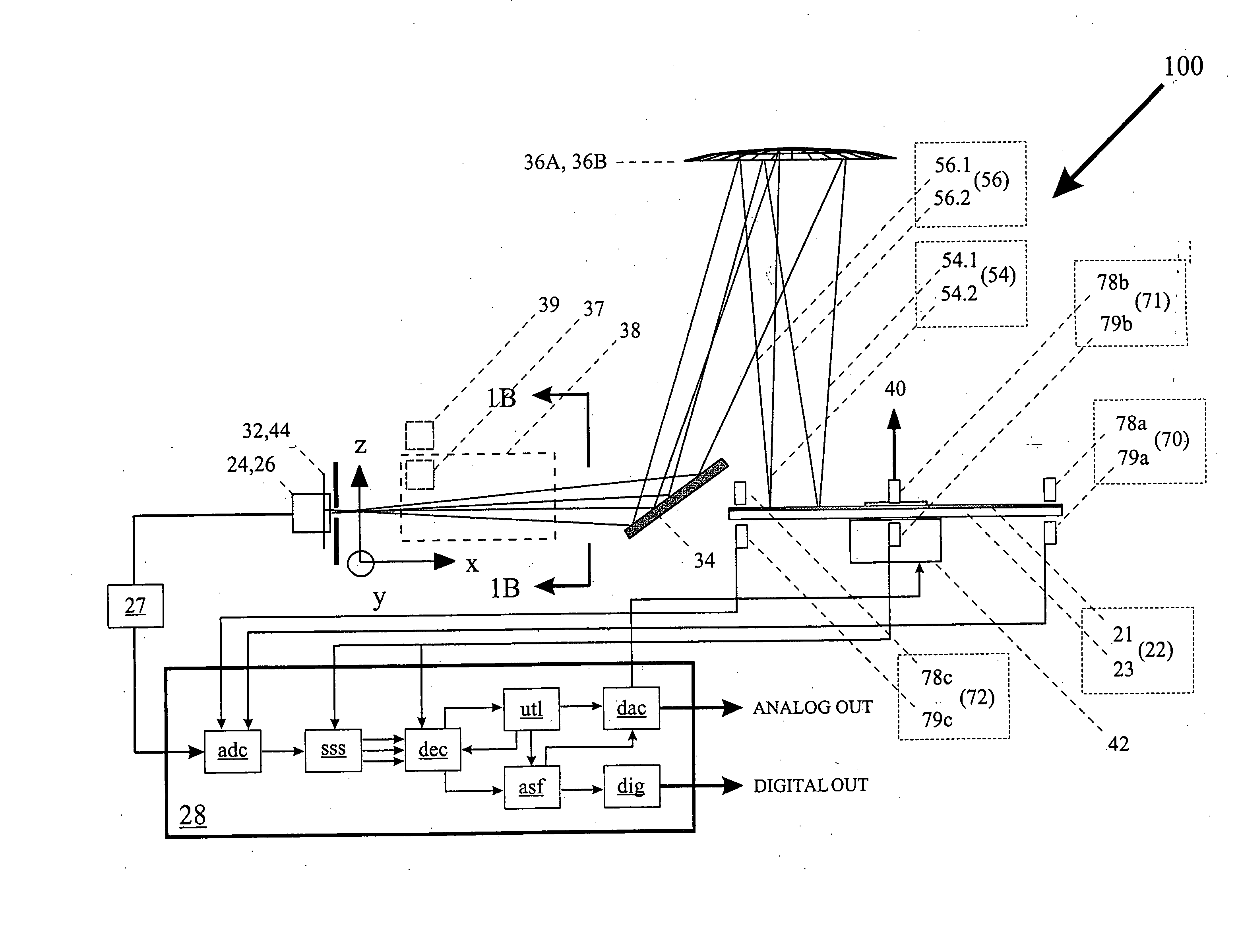
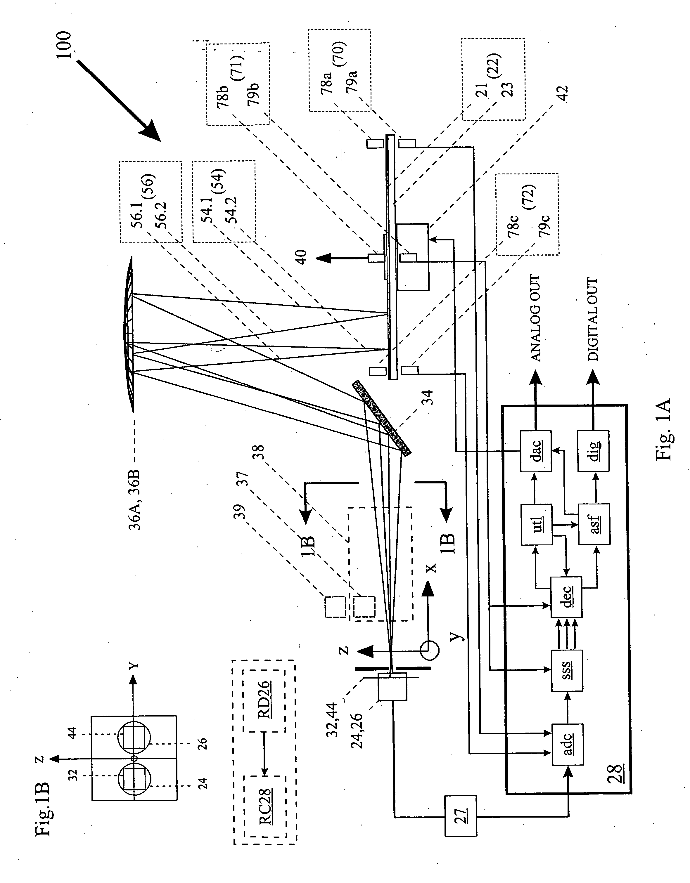
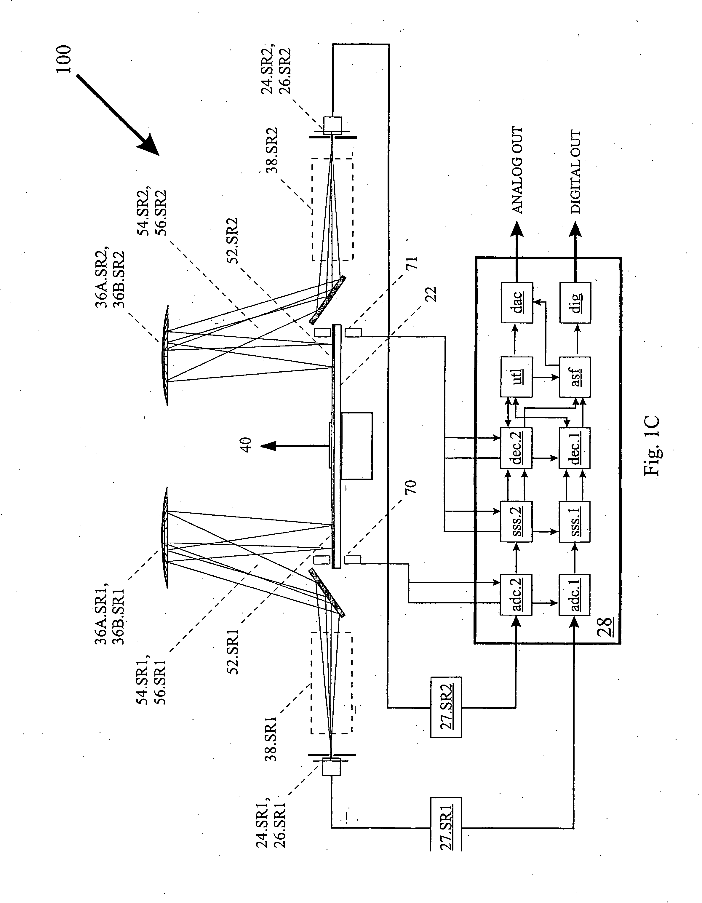
[0302] The first example of the multi-purpose analyzer 100 depicted in FIG. 1A, analyzer 100.1, is a multi-spectral-component encoded source with a high-intensity, collimated beam, which is used to measure radiation absorbing gasses and vapors in one or more long, open paths, such as gasses and vapors in FIG. 1A at 38 where the gasses and vapors are not confined by any enclosure. Examples of long, open paths include the atmosphere, the restricted air space between microwave transceivers, the line of sight between buildings or highway overpasses, between remote objects on the battlefield, and along the perimeter of a military compound or industrial facility. Radiation source 24.1 is a collimated radiation beam having a plurality of selected spectral components (e.g., a carbon dioxide laser). Pre-encoder optic 36A.1 includes at least one diffractive or refractive element to separate the selected spectral components to form target image 52.1 along a radial axis of modulator 22.1. Prefe...

example 2

[0307] The second example of the multi-purpose analyzer 100 depicted in FIG. 1A, analyzer 100.2, is a compact spectrum analyzer which uses a collection of bandpass filters or a linear variable filter (LVF) to provide a plurality of selected radiation components. In analyzer 100.2, the radiation source comprises a broad band or multi-wavelength source filtered by a linear array of two or more bandpass filters (or a linear array of two or more correlation radiometry filters; e.g., a collection of physical gas or liquid samples) or a linear variable filter (LVF). Taken together the radiation source and the collection of bandpass filters or LVF comprise extended source 24.2, having a number of spatial components corresponding to the radiation transmitted through (or reflected from) the individual bandpass filters or specific positions along the LVF. The radiation filtered by the array of bandpass filters or LVF is imaged by pre-encoder optic 36A.2 to form target image 52.2 substantially...

example 3

[0309] The third example of the multi-purpose analyzer 100 depicted in FIG. 1A, analyzer 100.3, is a spectrum analyzer, which is used for both analyzing and providing feedback to simultaneously control the center wavelengths of a number of tunable radiation sources. Radiation source 24.3 comprises a plurality of spectral components, where each spectral component corresponds to a distinct radiation source and is characterized by an intensity and a center wavelength. For example, radiation source 24.3 may be an optical fiber containing a plurality of optical signals, where each signal corresponds to a different radiation source. Radiation emitted by source 24.3 is imaged by pre-encoder optic 36A.3 to form a target image 52.3 onto modulator 22.3. Target image 52.3 comprises a plurality of sub-images focused at substantially different points along a radial axis of modulator 22.3, where each sub-image corresponds to a distinct radiation source. Pre-encoder optic 36A.3 comprises at least ...


PUM

PropertyMeasurementUnit
sizesaaaaaaaaaa
diameteraaaaaaaaaa
total lengthaaaaaaaaaa

Abstract

Method and apparatus for analyzing radiation using analyzers and employing the spatial modulation of radiation dispersed by wavelength or along a line.

Description

CROSS REFERENCE TO RELATED APPLICATIONS [0001] This application is a continuation-in-part of U.S. Provisional Application No. 60 / 361,967 filed Mar. 6, 2002, U.S. Provisional Application No. 60 / 413,424 filed Sep. 25, 2002 and U.S. Non-Provisional Application No. ______.BACKGROUND OF THE INVENTION [0002] This invention relates in general to radiation spectrum analyzers and radiation image analyzers, and in particular, to radiation analyzers and encoders employing the spatial modulation of radiation dispersed by wavelength or imaged along a line. [0003] Radiation spectral analysis is presently carried out in a number of ways. Dispersive and Fourier transform based analyzers are for high resolution and can be used for many different applications so that they are more versatile than existing application-specific instruments and procedures. While these analyzers offer superior spectral performance, they tend to be expensive, large, heavy and non-portable. For most applications, these inst...

Claims


Application Information

Patent Timeline
Patent Type & Authority Applications(United States)
IPC IPC(8): G01J3/04G01J3/18G01J3/02G01J3/28G01J3/42G01J3/433G01J3/44G01N21/27G01N21/35G01N21/64G01N21/65G01N27/447
CPCG01J3/02G01J2003/1217G01J3/0208G01J3/021G01J3/0216G01J3/0218G01J3/0229G01J3/027G01J3/0289G01J3/06G01J3/1804G01J3/2846G01J3/42G01J2001/4242G01J3/0202G01J3/04
Inventor HAGLER, THOMAS
Owner MUDLOGGING SYST
Why Eureka
Try Eureka