[0007]This invention provides many advantages over the
radiation analyzers described above. In some embodiments, the intensity of the incident radiation is modulated independent of the bandwidth and that the amplitude of the modulated signal is a smooth function or changes between three or more distinct levels of contrast as the modulator is rotated about an axis or otherwise reciprocated. One can implement a multi-channel orthogonal encoding scheme for arbitrary center wavelengths and bandwidths and arbitrary radial intensity distributions. In this manner, the center wavelengths and bandwidths of the encoded channels can be independently optimized for a specific application. The before mentioned optical encoding scheme is combined with imaging
optics so that radiation from an extended source or collection of discrete samples can be imaged using a single detector. This allows one to control the modulation depth on a channel-by-channel basis independent of the bandwidth, a
design strategy which may be useful for balancing signal levels in systems where one or more channels have a disproportionately large fraction of the total incident radiation. This allows one to group modulation channels into complementary pairs where the amplitude and phase of the resulting encoded component are determined by the relative portion of radiation incident on the two filters comprising the pair. In this manner, intensity differences,
wavelength derivatives, and the
radial position of the center of an intensity distribution can be measured directly. This allows one to use one or more
complementary filter pairs in conjunction with an expected radiation component for calibration and alignment purposes. One may also use a dedicated
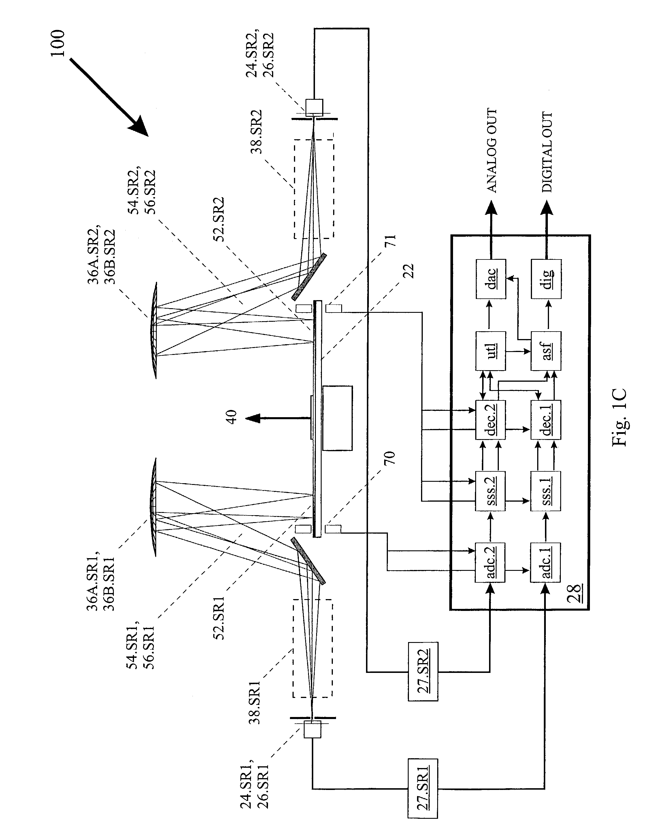
light source and detector and a series of marks on the modulator to detect spindle wobble, vibrations or a misaligned modulator pattern on the modulator substrate for calibration and alignment purposes. One can also measure a plurality of response radiation components as a function of two or more excitation components substantially simultaneously, enabling a fast, compact
fluorescence, Raman or photo-refractive excitation / response analyzer. It is possible to use modulation functions which are based on incomplete periods of the rotation of the modulator, which can be used to eliminate various hardware items, free up micro-processor resources, synchronize the movements of external
mechanical devices, measure both the
radial position and the intensity of an imaged radiation component, and increase the spatial or
spectral resolution of the analyzer. Finally, one may measure a plurality of spectral components individually selected from a collection of radiation emitting samples substantially simultaneously using a one-dimensional hyper-
spectral imaging optic and a single channel detector.
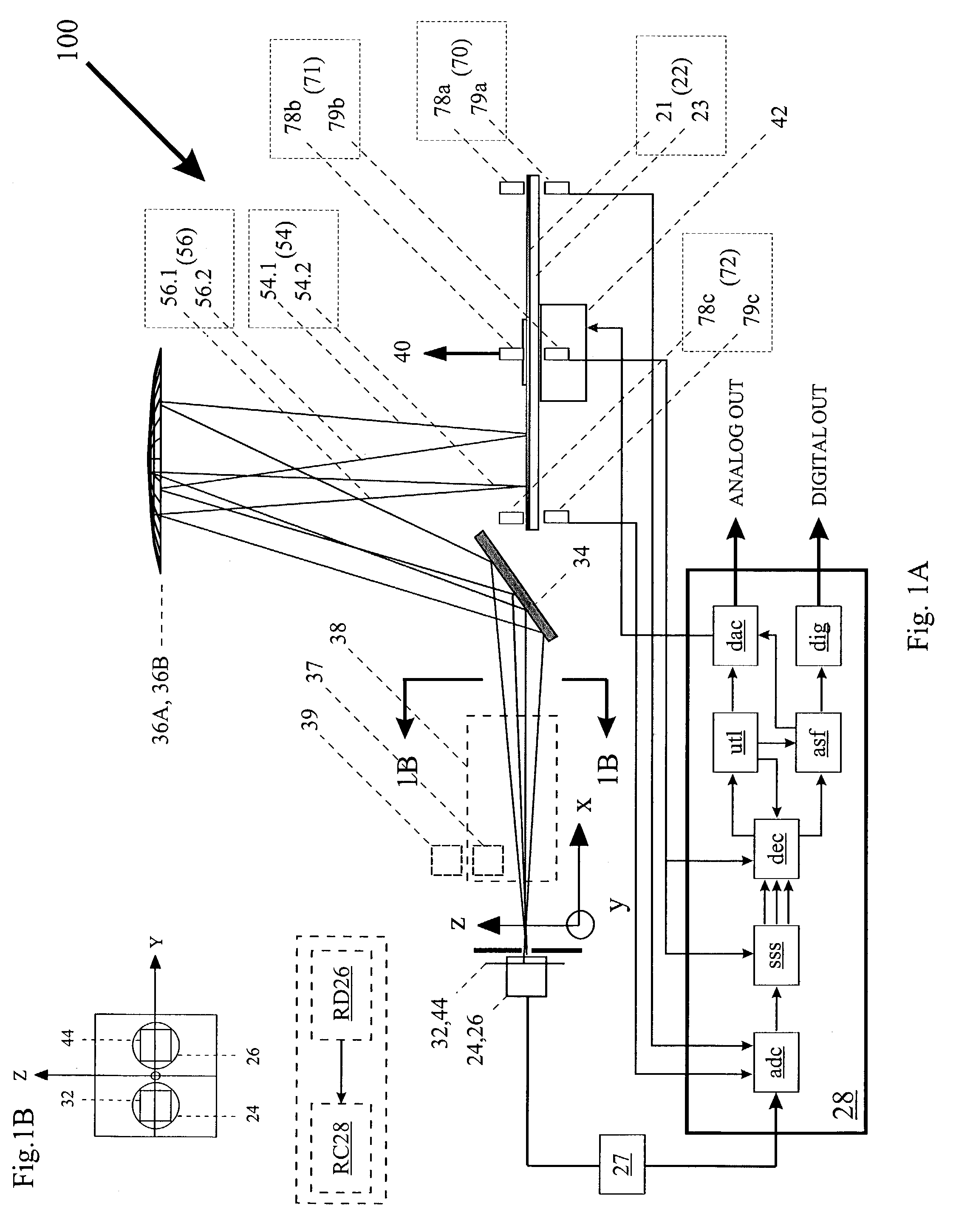
[0010]In the preferred embodiment of the spectrum and imaging analyzers described above, the two-dimensional spatial radiation modulator contains a series of timing marks and the analyzer has a number of optical switches which are triggered by the timing marks to establish the absolute
angle of rotation for decoding purposes. Most preferably, the timing marks will also trigger the
data acquisition (DAQ) from the detector and the decoding
algorithm, which in turn, will substantially relax any stability requirements of the modulators rotational period. Preferably, the analyzer will have a dedicated radiation source and an analog detector which is partially interrupted by the timing marks and / or other marks located on the modulator or spindle to detect spindle wobble or a misaligned pattern on the modulator. More preferably, the signal generated by the analog detector are processed by the computer to provide the decoding
algorithm and / or the analytical function with one or more calibration coefficients used to compensate for the undesired effects of spindle wobble or a misaligned pattern. Most preferably, the signal generated by the analog detector are processed by the computer to provide a
control signal to position of one or more optical elements to keep the image or dispersed image centered on the modulator pattern.
[0011]In the preferred embodiment of the spectrum and imaging analyzers described above, the analyzers computer will include a transient-signal
algorithm that will detect transients in the amplitudes of the encoded components which occur during a rotational period of the modulator. Preferably, the computer will analyze the
transient signal to determine its
harmonic content. More preferably, the
harmonic content will be used by the decoding algorithm to compensate for transient-induced
harmonic interference. Preferably, the transient-signal algorithm will include a feedback mechanism to increase the
motor speed in response to the detection of sub-rotational-period signal transients and decrease the
motor speed in response to extended periods of time where the amplitudes are stable.
[0012]Another aspect of the invention and useful for the above-described spectrum and image analyzers is a spatial radiation modulator adapted to be rotated about a rotation axis to modulate at least one component of an incident
radiation beam to provide an encoded beam. The modulator comprises a substrate and at least one radiation filter located at a
radius from the rotation axis. The filter comprises an annular region substantially encompassing a plurality of pixels having optical characteristics substantially different from the substrate. The pixels are patterned substantially within the annular region to modulate the intensity of a corresponding radiation component predominantly along an azimuthal axis to provide an encoded component such that the amplitude of the encoded component changes between three or more substantially distinct levels of contrast as the substrate is rotated about the rotation axis. Preferably, the density of the pixels is used to control the modulation depth of the encoded component. In this manner, the amplitudes of two or more encoded components can be balanced when one of the components has a disproportionate fraction of the total incident radiation.
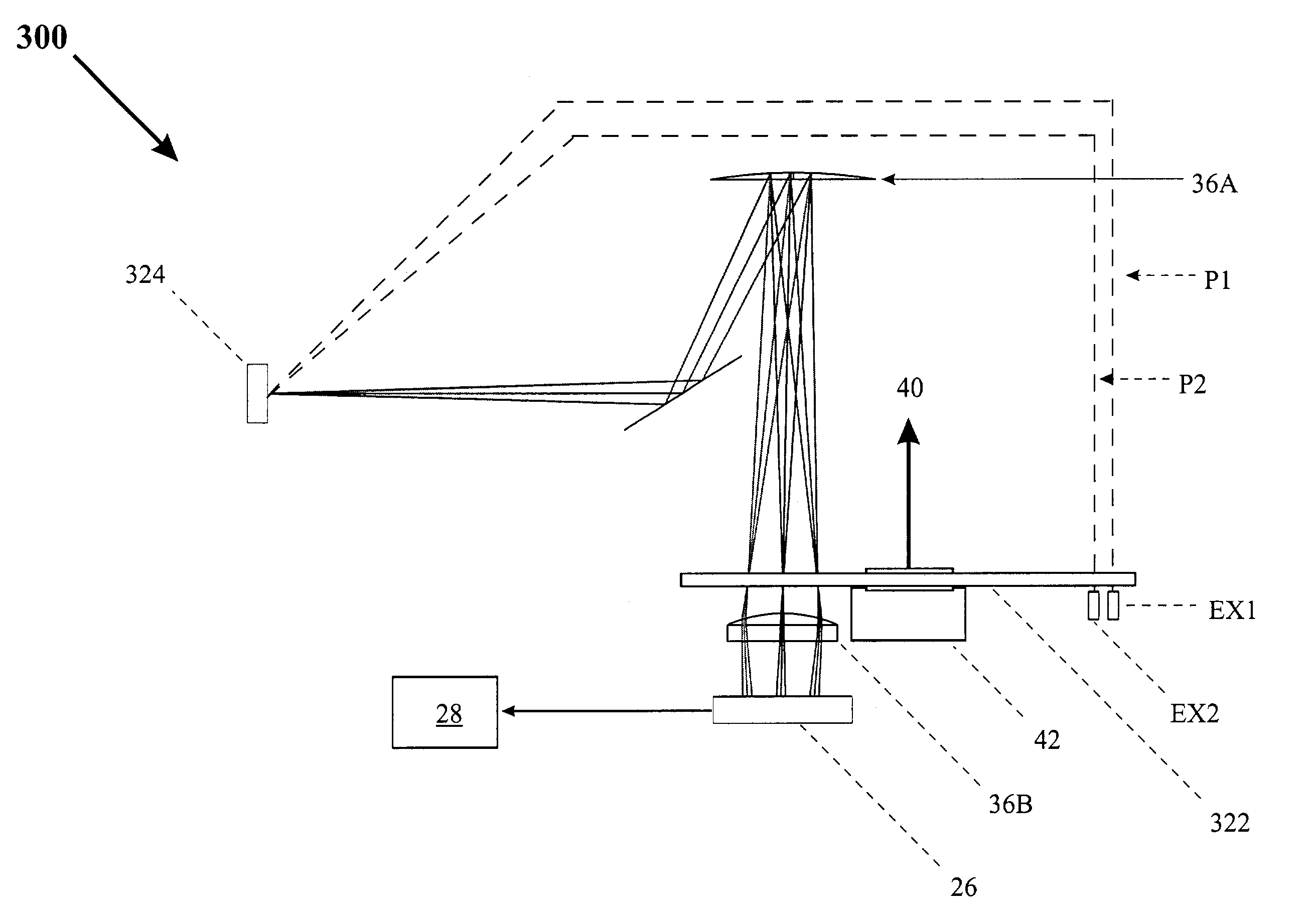
[0019]In one embodiment, a radiation
spectrum analyzer employs a bi-conic optical element to reduce the
optical path length between the modulator and the detector, and / or to increase the collection efficiency. The curvature of the bi-conic optical element may be chosen so as to increase the collection efficiency.
[0032]In still one more embodiment, rotation frequency of a modulator of the type described above is controlled. Signals generated by a detector detecting modulated signals are analyzed, wherein the analyzing includes decoding at least one
noise tracking signal originating from a periodic noise source. The rotation frequency of the modulator is varied to maximize an amplitude of the noise tracking signal and thereby minimize the effect of the periodic noise source on the decoded amplitudes of certain encoded components.

