Fuel Cell System
- Summary
- Abstract
- Description
- Claims
- Application Information
AI Technical Summary
Benefits of technology
Problems solved by technology
Method used
Image
Examples
first embodiment
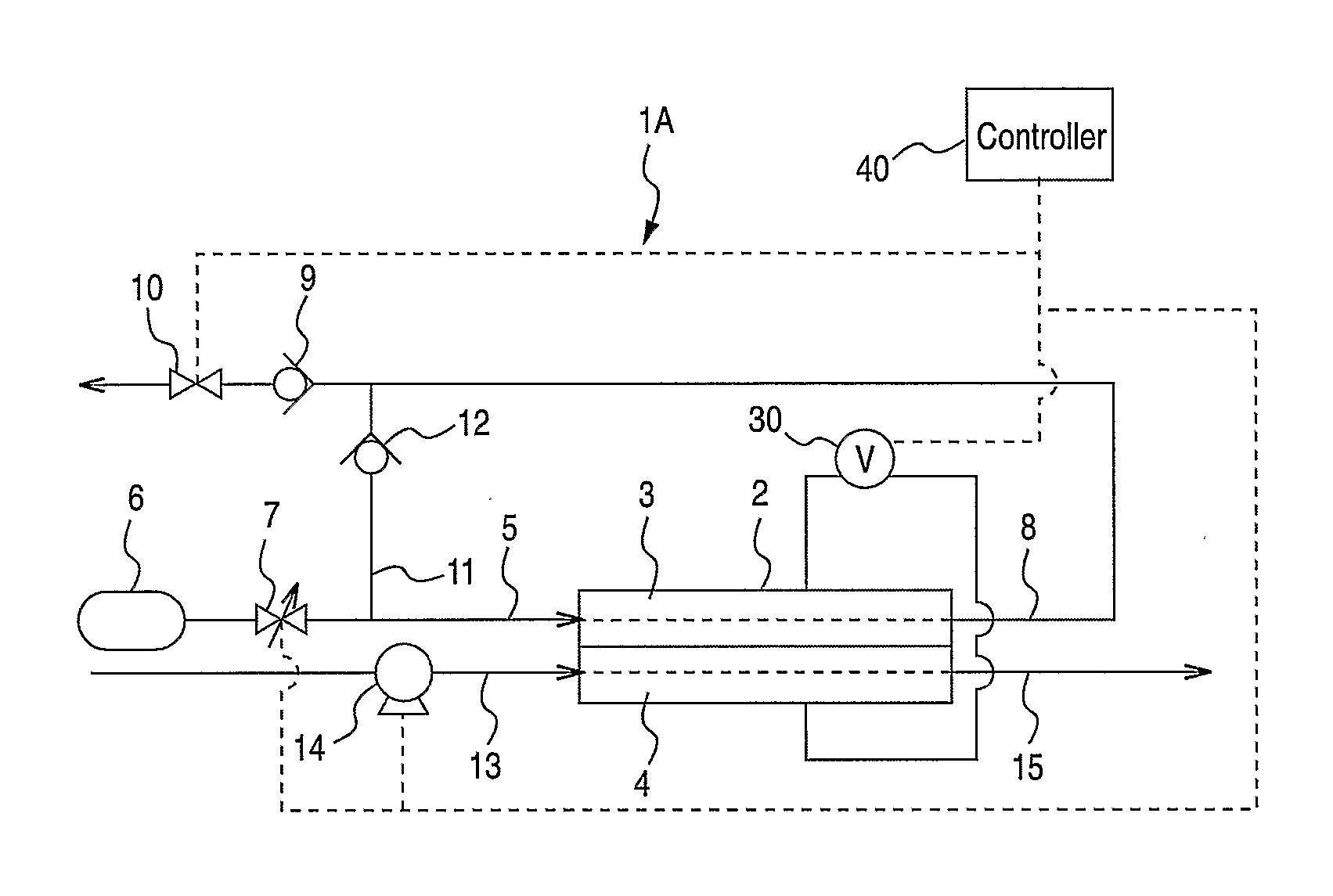
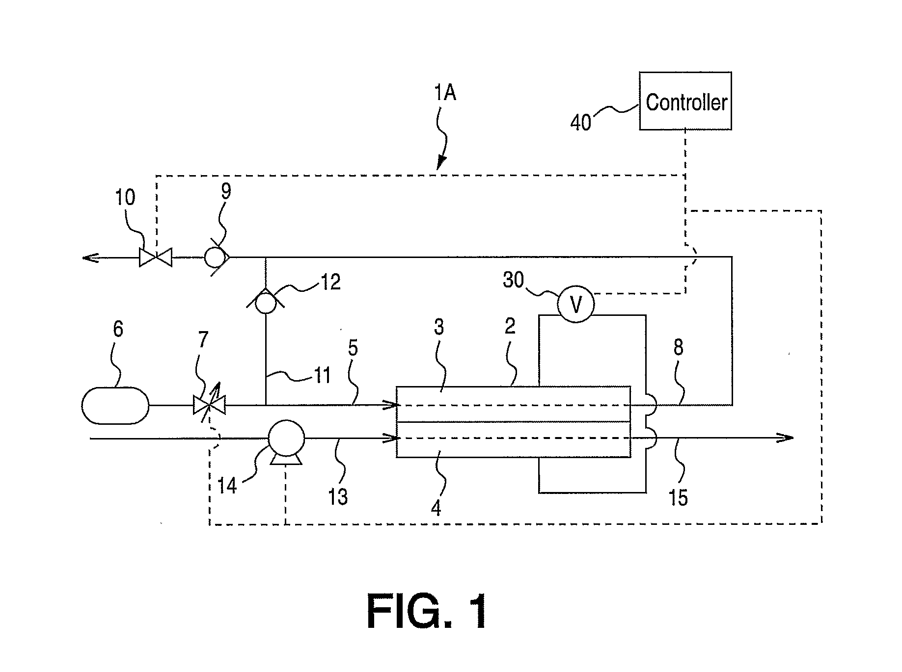
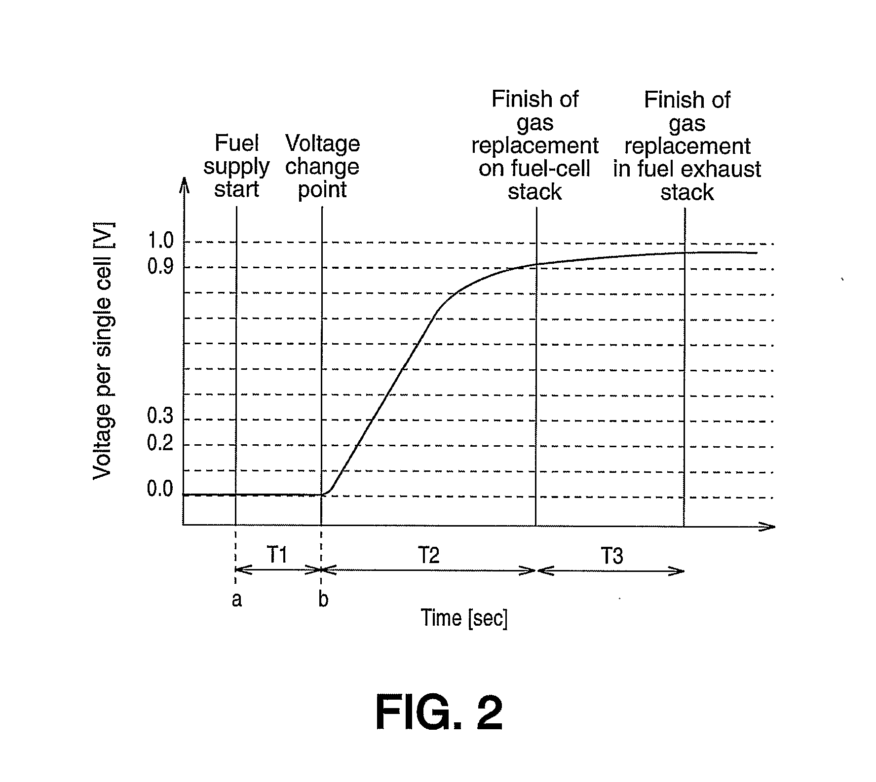
[0021]FIG. 1 is a schematic diagram of a fuel cell system 1A. FIG. 2 is a characteristic line graph showing voltage of fuel cell stack 2 upon start of the fuel cell and illustrates an estimation procedure of the gas replacement completion time.
[0022] In FIG. 1, fuel cell system 1A is equipped with fuel cell stack 2. Fuel cell stack 2 is equipped with fuel electrode 3 facing the fuel chamber and oxidizer electrode 4 facing the oxidizer gas chamber. In fuel cell stack 2, the voltage detection means 30 (for example, a voltage sensor) is electrically connected to the fuel cell system 1A and detects a voltage produced by the electric power generation of fuel electrode 3 and oxidizer electrode 4. The voltage detected by the voltage detection means 30 is output to a controller 40.
[0023] With respect to fuel gas supply conduit (e.g. fuel gas supply means) 5, one end is connected to fuel tank 6, and the other end is connected to the entry of the fuel chamber of the fuel cell stack 2. Fuel g...
second embodiment
[0054] Also, since circulation compressor 20 utilized as in the second embodiment, the fuel gas is more effectively circulated in fuel gas recirculation conduit 11. The fuel gas vent valve 10 is closed at the estimated gas replacement completion time T, but the valve for the fuel gas recirculation conduit 21 is closed sooner.
PUM
 Abstract
Description
Claims
Application Information
 - Generate Ideas
- Intellectual Property
- Life Sciences
- Materials
- Tech Scout
- Unparalleled Data Quality
- Higher Quality Content
- 60% Fewer Hallucinations
Browse by: Latest US Patents, China's latest patents, Technical Efficacy Thesaurus, Application Domain, Technology Topic, Popular Technical Reports.
© 2025 PatSnap. All rights reserved.Legal|Privacy policy|Modern Slavery Act Transparency Statement|Sitemap|About US| Contact US: help@patsnap.com


