Low vapor pressure fuels for use in catalytic burners
a technology of low vapor pressure fuel and catalytic burner, which is applied in the direction of capillary burner, combustion type, lighting and heating apparatus, etc., can solve the problems of clogging and stopping operation of catalytic burners, and the current use of fuel mixtures will likely face severe use restrictions
- Summary
- Abstract
- Description
- Claims
- Application Information
AI Technical Summary
Benefits of technology
Problems solved by technology
Method used
Image
Examples
working examples
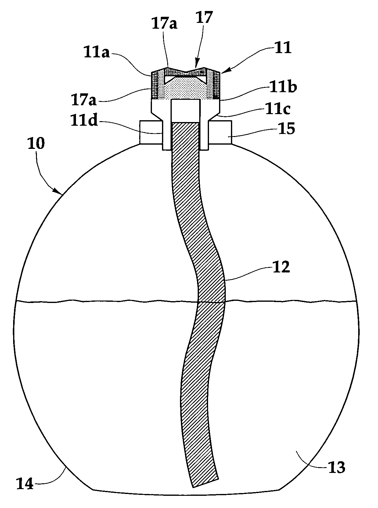
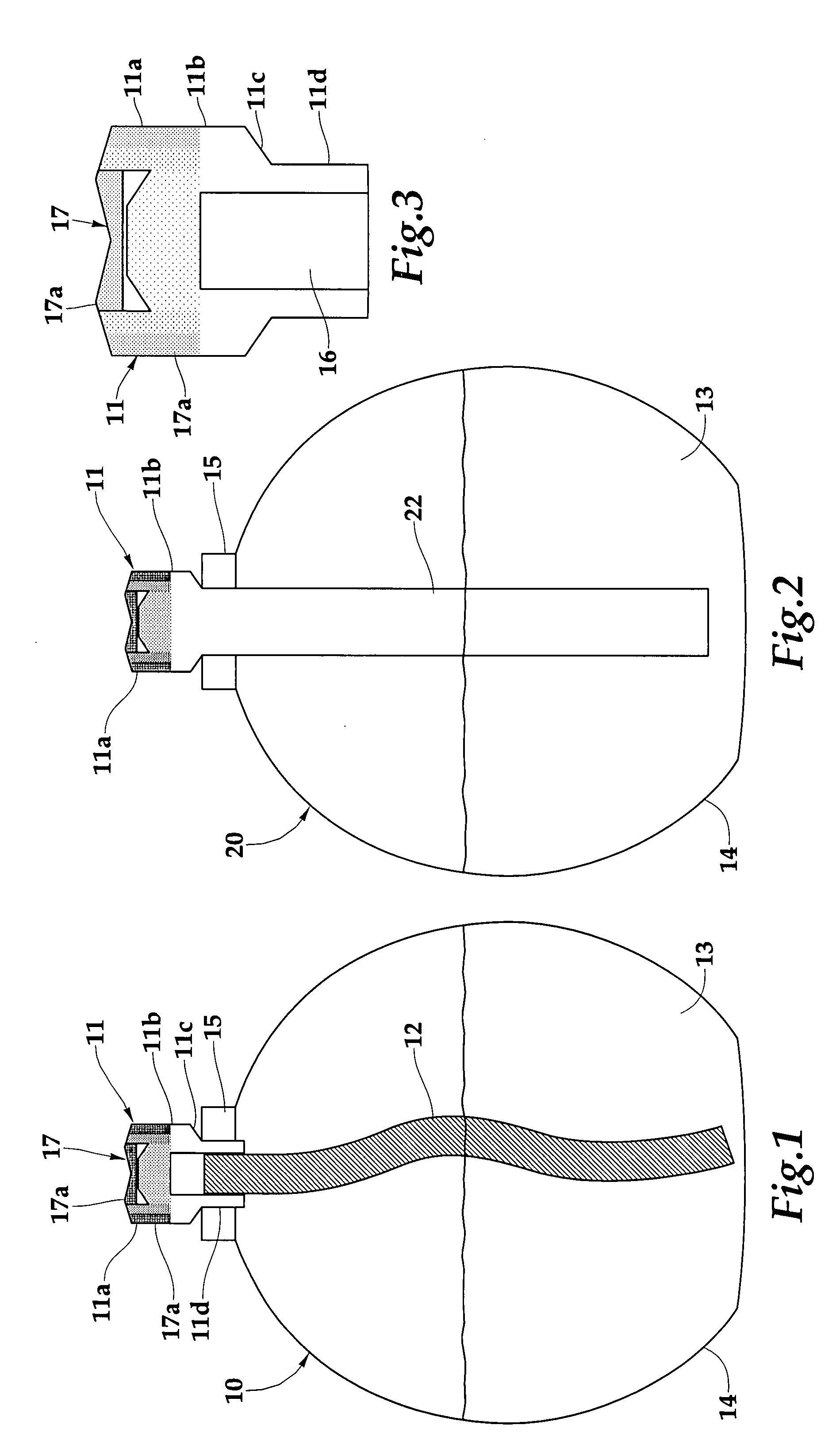
[0048] To determine the suitability of a fuel for use with flameless catalytic lamps all fuels were tested under the following conditions. All fuels were combusted using a catalytic burner composed of 82 wt % zeolite (ZSM-5, Si / Al=220), 15 wt % borosilicate glass, 2 wt % bentonite, and 1 wt % boron nitride. The burner was formed into the pyramid shape and fired at 1000° C. The burner was treated with a platinum-rhodium (70:30 mol %, respectively) solution, the silicon to catalyst ratio was 27. All fuels were mixed with 2-propanol and fragrance oil prior to testing. A typical composition is 75.2 ml LVP fuel, 23.7 ml 2-propanol, and 1.1 ml lemongrass sage fragrance oil (80:18:2 wt %, respectively).
example 1
Commercially Available LVP Fuels
[0049] Low vapor pressure fuel mixtures are composed of 80 wt % LVP fuel, 18 wt % alcohol, and 2 wt % fragrance oil. The commercially-available LVP fuels (Table 1) were used as received. A typical composition is 75.2 mL LVP fuel, 23.7 mL 2-propanol, and 1.1 mL lemongrass sage fragrance oil. The resulting mixture is burned by the aforementioned catalytic burner to emit fragrance.
[0050] Table 2 shows the compounds tested as commercially available LVP fuels along with their properties. Compound 1 showed the best properties for use as a low vapor pressure fuel of all the fuels tested, including biodiesels and synthetic fuels. The operating temperature of Compound 1 was 274° C., which was the highest of the fuels tested. It also produced no soot during ignition and also the lowest amount of smoke of any of the compounds. After several trials there was no noticeable coke build-up.
[0051] Compounds 2 and 3 had similar operating temperatures at 252 and 251°...
example 2
Synthetic LVP Fuels
[0054] Low vapor pressure fuel mixtures composed of synthetic fuels were prepared as follows. The synthetic LVP fuels (Table 3) were synthesized from a condensation reaction utilizing an acid chloride and an alcohol or diol. In a typical reaction, 77.9 mL of diethylene glycol is dissolved in 150 mL dichloromethane and added to a round bottom flask. Then, 33.2 mL of ethyl chlorooxoacetate is dissolved in 150 mL dichloromethane and added to a constant pressure addition funnel. The ethyl chlorooxoacetate solution is added dropwise, at room temperature, to the stirring diethylene glycol solution. The reaction is allowed to proceed at room temperature for 6 hours. The solution is then poured in a separatory funnel and washed with 600 mL of saturated sodium bicarbonate solution. The organic layer is then separated and dried over magnesium sulfate. The magnesium sulfate is filtered off and the organic layer collected. The dichloromethane is removed via rotary evaporatio...
PUM
 Abstract
Description
Claims
Application Information
 - R&D
- Intellectual Property
- Life Sciences
- Materials
- Tech Scout
- Unparalleled Data Quality
- Higher Quality Content
- 60% Fewer Hallucinations
Browse by: Latest US Patents, China's latest patents, Technical Efficacy Thesaurus, Application Domain, Technology Topic, Popular Technical Reports.
© 2025 PatSnap. All rights reserved.Legal|Privacy policy|Modern Slavery Act Transparency Statement|Sitemap|About US| Contact US: help@patsnap.com


