Magnetic resonance imaging apparatus

a magnetic resonance imaging and apparatus technology, applied in the field of magnetic resonance imaging apparatus, can solve the problems of deteriorating s/n ratio of the signal received by the receiver, increasing the length of the received signal cable connected to the lower coil, and taking time to position, so as to reduce the factor obstructing the coil performance, easy to choose, and convenient to position objects

Inactive Publication Date: 2008-01-17
TOSHIBA MEDICAL SYST CORP
View PDF5 Cites 36 Cited by
  • Summary
  • Abstract
  • Description
  • Claims
  • Application Information

AI Technical Summary

Benefits of technology

[0017]The present invention has taken into consideration the above-described problems, and it is an object of the present invention to provide a magnetic resonance imaging apparatus, a positioning of an object becomes easy, it becomes easy to choose the most suitable coil, and can reduce a factor to obstruct performance of the coil.

Problems solved by technology

Firstly, in the imaging of the whole body, for example, the moving distance of the lower coil needs to be at least the sum of the height of the patient and the distance from the leading end to the center of the gantry. Thus, the received signal cable connected to the lower coil is increased in length. As a result, the S / N ratio of the signal received by the receiver is deteriorated.
Secondly, the patient needs to be positioned in accordance with the lower coil, and the positioning takes time. Further, the burden on the patient caused by the time taken for the positioning is large.
Thirdly, the coil on the table-top is displaced from the coil position optimized for each of the sites, depending on the physical size of the patient. As a result, good imaging is prevented.
Fourthly, since the coil is provided on the table-top, an extra coil set is required for a stretcher in which the patient is previously positioned on the table-top.
Fifthly, in the use of the special RF coil for imaging a local site, the RF coil is coupled with the coil provided on the table-top. As a result, the performance of the coils cannot be optimized.

Method used


Image

  • Magnetic resonance imaging apparatus
  • Magnetic resonance imaging apparatus
  • Magnetic resonance imaging apparatus

Examples


first embodiment

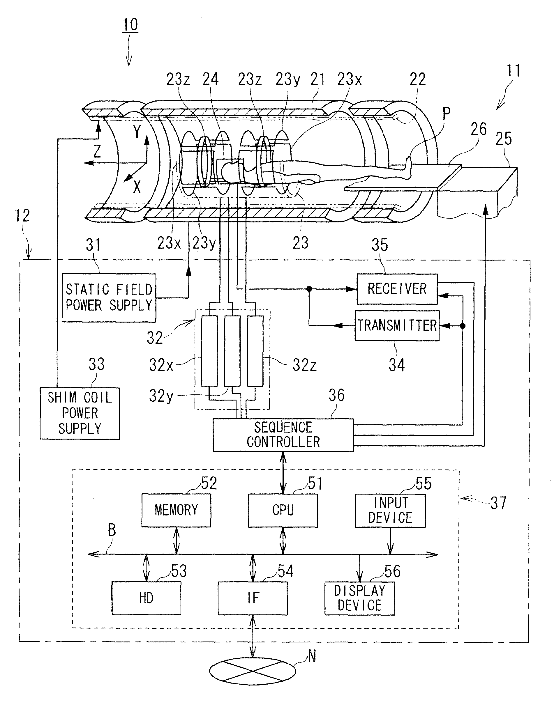
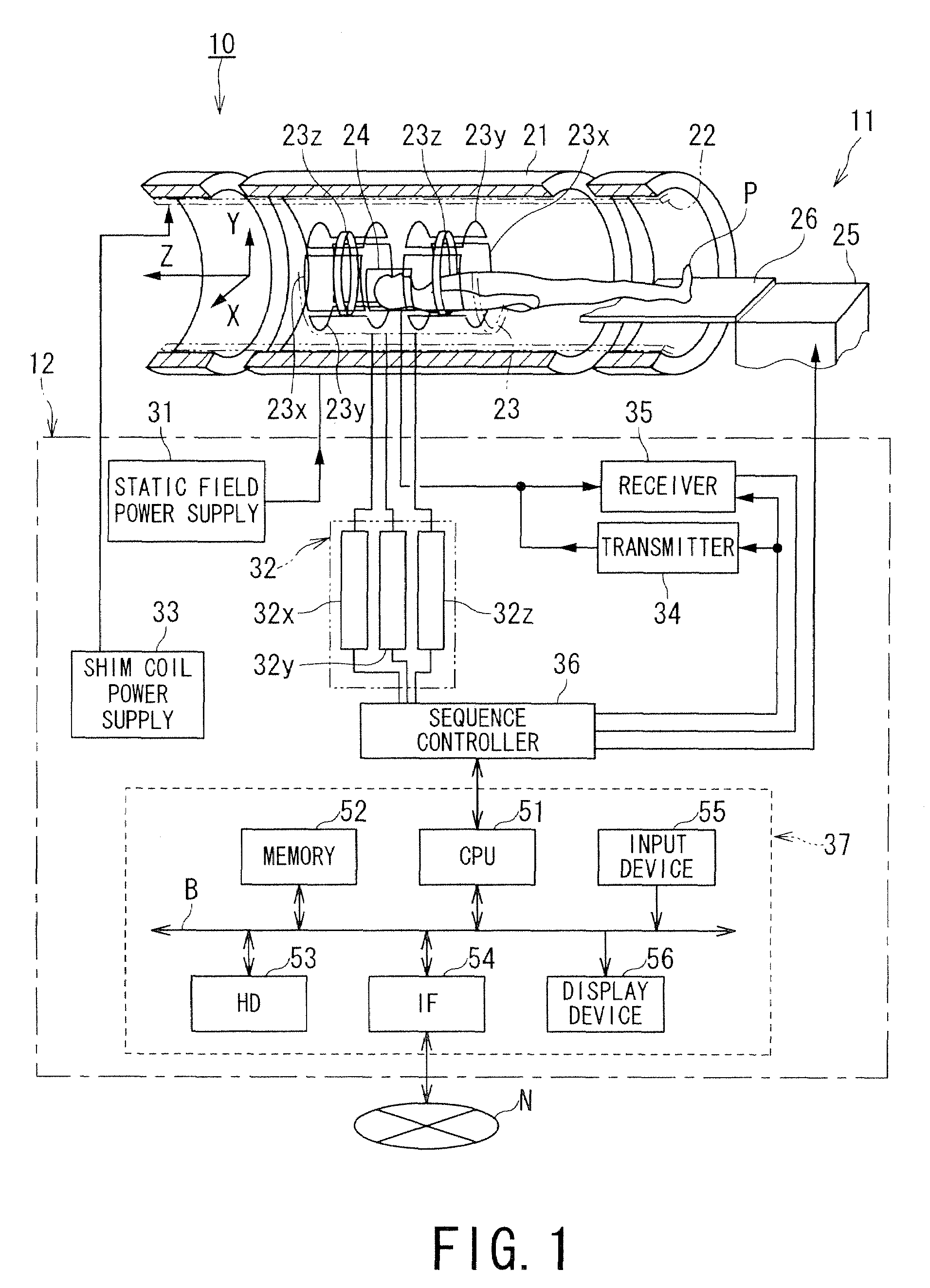
[0057]FIG. 1 is a schematic view illustrating a configuration of a first embodiment of the MRI apparatus according to the present invention.

[0058]FIG. 1 illustrates an MRI apparatus 10 according to the first embodiment, which images a patient (an object) P while continuously moving the patient P. The MRI apparatus 10 is mainly formed by an imaging system 11 and a controlling system 12.

[0059]The imaging system 11 of the MRI apparatus 10 is provided with a gantry (not illustrated). The gantry stores therein a static field magnet 21, a cylindrical shim coil 22 provided inside and coaxial with the static field magnet 21, and a gradient coil unit 23 formed into a cylindrical shape and provided inside the static field magnet 21. Further, the imaging system 11 is provided with an RF coil 24 for transmitting a high-frequency (RF: radio frequency) signal having the Larmor frequency (resonant frequency), and a bed structure 25 for advancing and retreating the patient P with respect to the ins...

second embodiment

[0129]The configuration of an MRI apparatus 10A according to a second embodiment is the same as the configuration of the MRI apparatus 10 illustrated in FIG. 1. Thus, description thereof will be omitted. Further, similarly to the case of the MRI apparatus 10, FIGS. 2 to 5 also apply to the MRI apparatus 10A.

[0130]FIG. 21 is a cross-sectional view as viewed from a side, illustrating the positional relationship of the table-top 26 and the lower coil 24c and a movement control unit for controlling the movement of the lower coil 24c in the horizontal direction. FIG. 22 is a cross-sectional view as viewed from above, illustrating the movement control unit for controlling the movement of the lower coil 24c in the horizontal direction. FIG. 23 is an arrow view along the XXIII-XXIII line, illustrating the movement control unit for controlling the movement of the lower coil 24c in the horizontal direction. In FIGS. 21 to 35, description will be made by taking an example in which the RF coil ...


PUM


Abstract

A magnetic resonance imaging apparatus has a static field magnet, gradient coils, a gantry including an opening and storing the static field magnet the gradient coils, a bed structure for advancing and retreating a table-top, on which an object can be placed, with respect to the opening, a lower coil formed by a radio frequency coil disposed below the table-top, and a movement control unit configured to control the lower coil to be movable.

Description

BACKGROUND OF THE INVENTION[0001]1. Field of the Invention[0002]The present invention relates to a magnetic resonance imaging apparatus which magnetically excites the nuclear spin of an object with a high-frequency (RF) signal having the Larmor frequency and reconstructs an image from a magnetic resonance signal generated along with the excitation.[0003]2. Description of the Related Art[0004]A medical imaging apparatus provides a large amount of information on a patient in the form of an image, and plays an important role in many medical practices including the diagnosis of a disease, the treatment, and the operation planning. Currently, major medical imaging apparatuses include an ultrasonic diagnostic apparatus, an X-ray CT (computerized tomography) apparatus, a magnetic resonance imaging (hereinafter referred to as MRI) apparatus, and a nuclear medicine diagnostic apparatus. In particular, the MRI apparatus can collect a high-quality contrast image of soft tissue, and occupies an...

Claims


Application Information

Patent Timeline
Patent Type & Authority Applications(United States)
IPC IPC(8): A61B5/055
CPCG01R33/307G01R33/56375G01R33/3415G01R33/34084
Inventor TAKAMORI, HIROMITSU
Owner TOSHIBA MEDICAL SYST CORP
Why Eureka
Try Eureka