

System and method for cooling hydrocarbon-fueled rocket engines
- Summary
- Abstract
- Description
- Claims
- Application Information
AI Technical Summary
Benefits of technology
Problems solved by technology
Method used
Image

Examples
Embodiment Construction
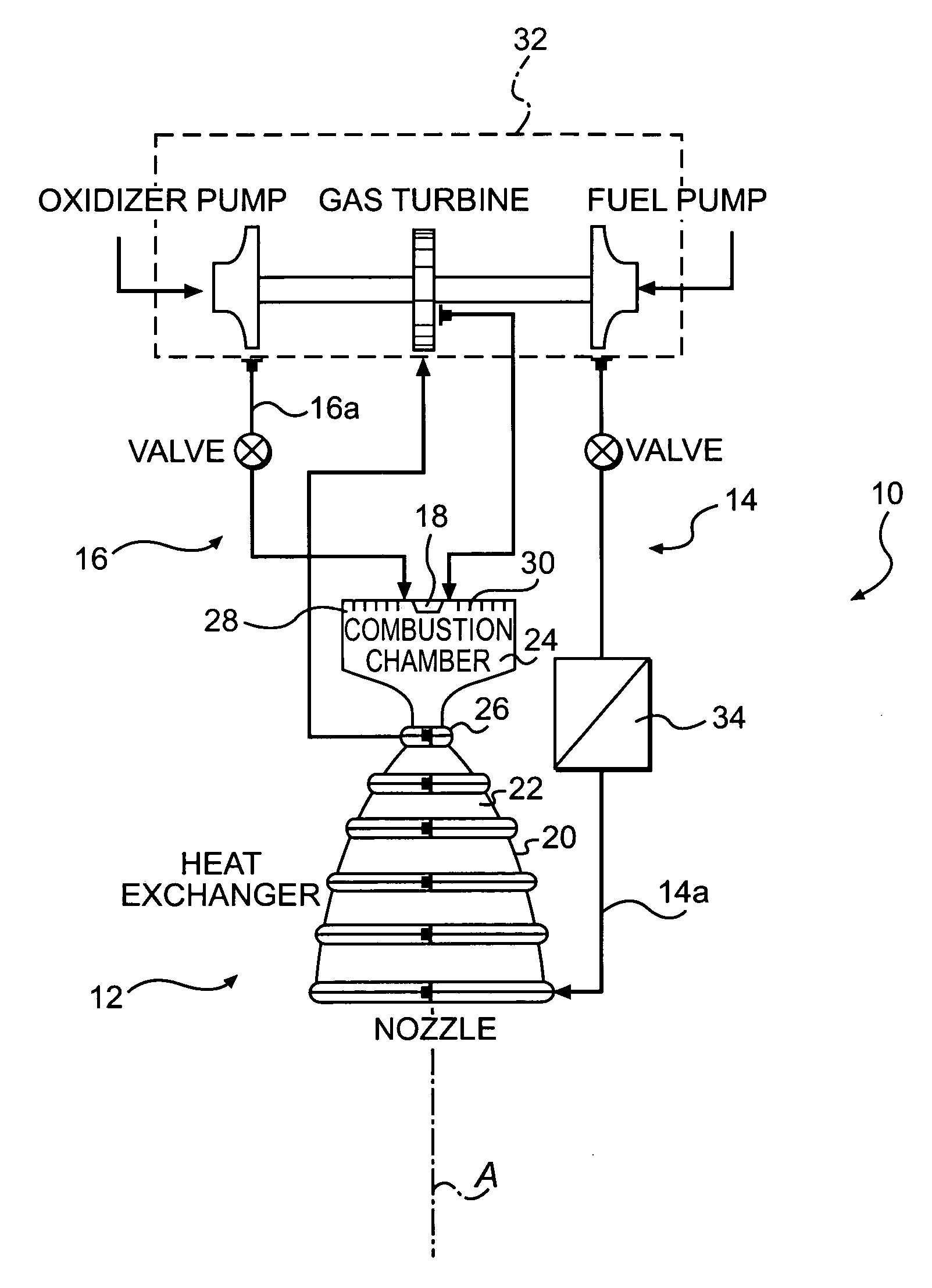
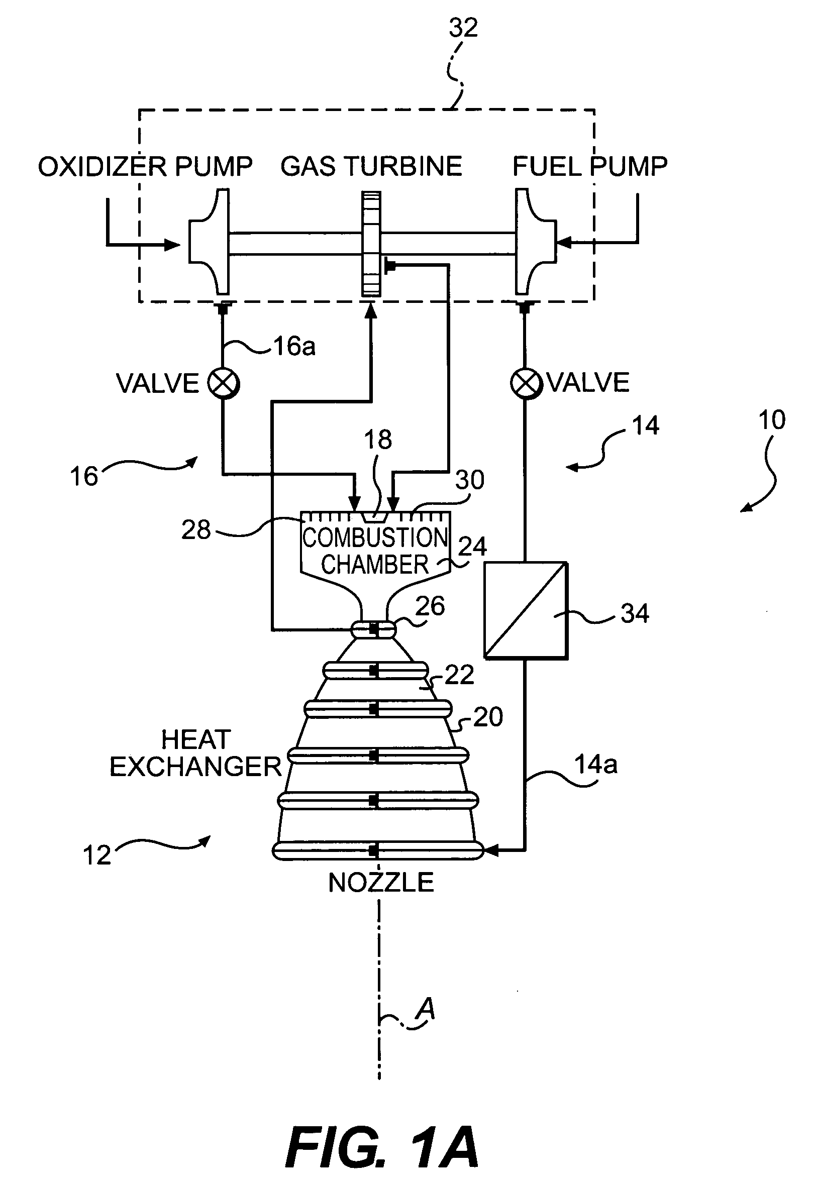
[0014]FIG. 1A illustrates a schematic view of a rocket engine 10. The engine 10 generally includes a nozzle assembly 12, a fuel system 14, an oxidizer system 16 and an ignition system 18. The fuel system 14 and the oxidizer system 16 preferably provide a gaseous propellant system of the rocket engine 10, however, other propellant systems such as liquid will also be usable with the present invention. It should be further understood that although an expanded cycle type rocket engine is illustrated in the disclosed embodiment other rocket engine power cycle types including but not limited to Gas-generator cycle, Staged combustion cycle, and Pressure-fed cycle will also benefit from the present invention.
[0015]A combustion chamber wall 20 about a thrust axis A defines the nozzle assembly 12. The combustion chamber wall 20 defines a thrust chamber 22, a combustion chamber 24 upstream of the thrust chamber 22, and a combustion chamber throat 26 therebetween. The nozzle assembly 12 include...
PUM
 Abstract
Description
Claims
Application Information