
Drill for machining fiber reinforced composite material

Inactive Publication Date: 2008-01-24
KENNAMETAL INC
View PDF45 Cites 51 Cited by
  • Summary
  • Abstract
  • Description
  • Claims
  • Application Information

AI Technical Summary

Benefits of technology

[0005]Briefly, according to this invention, there is provided a split-point, two-fluted twist drill for machining fiber reinforced composite material. The drill has a lip relief angle between about 10 and 20 degrees; a notch rake angle of between about −5 and 10 degrees; a chisel edge length up to about 0.035 mm; a chisel edge angle of between about 105 and 120 degrees; a splitting angle between about 130 and 150 degrees; and a point angle of between about 70 and 100 degrees.
[0006]In another embodiment, a split-point diamond coated twist drill for machining fiber reinforced composite material made of a substrate comprised of tungsten carbide cemented with cobalt in a range between about 3 to 10 wt. %, wherein said drill has a point angle of about 90 degrees.
[0007]In yet another embodiment, a split-poi

Problems solved by technology

However, CFRP composite materials pose tremendous problems in machining.
In addition, due to the high strength of the fiber reinforcement, CFRP is extremely abrasive, which requires tools to have excellent hardness.

Method used


Image

  • Drill for machining fiber reinforced composite material
  • Drill for machining fiber reinforced composite material
  • Drill for machining fiber reinforced composite material

Examples


Embodiment Construction

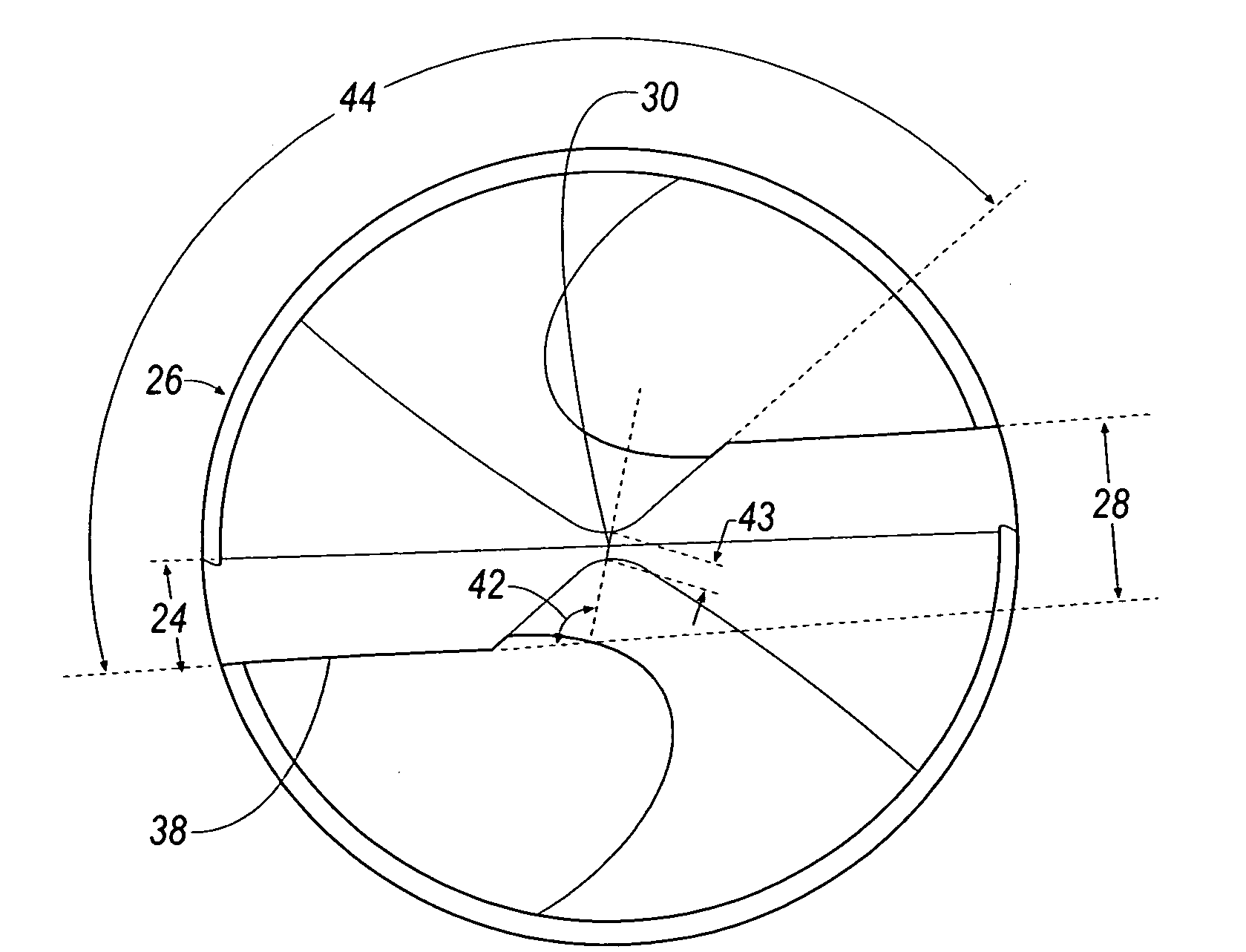
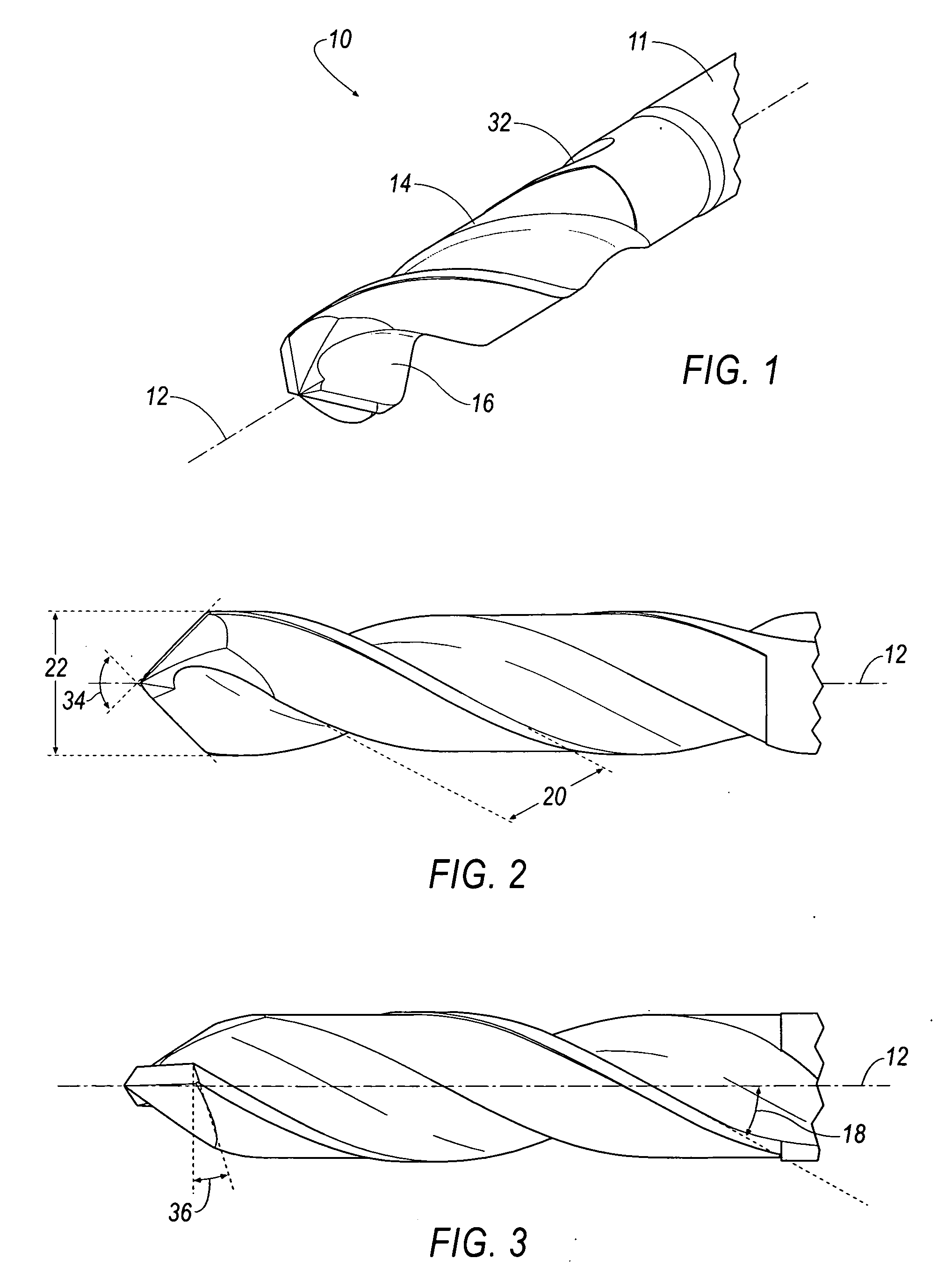
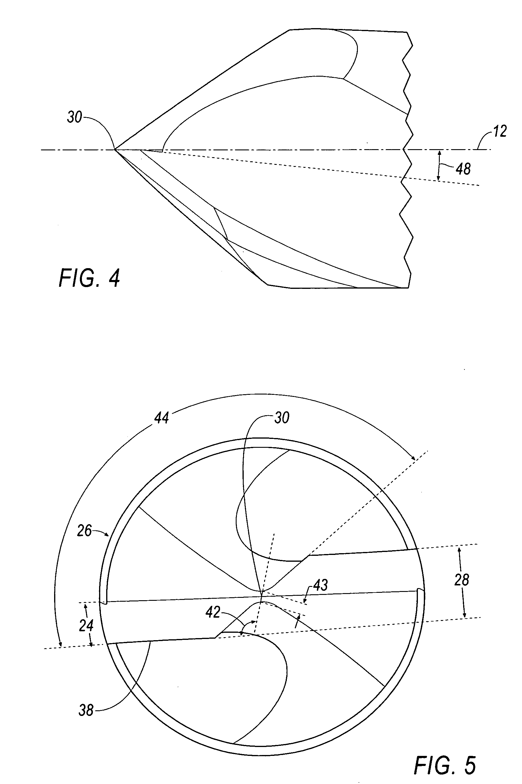
[0017]Referring to FIGS. 1-5, wherein like reference characters represent like elements, a two-fluted, diamond coated twist drill prior to splitting is generally shown at 10 according to an embodiment of the invention. Preferably, the drill 10 is made from a tungsten carbide (WC) substrate with cemented cobalt (Co) in a range between about 3 to 10 wt. % and a diamond coating having a thickness in a range between about 3 to 20 μm deposited by using a chemical vapor deposition (CVD) process. The hone radius (or cutting edge radius) is between about 5 to 30 microns after coating.

[0018]The drill 10 has a shank 11, a longitudinal axis 12 and includes two flutes, 14 and 16, at a helix angle 18 that is in a range between about 25 and 35 degrees with respect to the longitudinal axis 12. A margin width 24 is maintained between about 5 to 10 percent of the drill diameter 22. A body clearance diameter 26 is maintained at between about 92 to 96 percent of the drill diameter 22. A web thickness ...


PUM

PropertyMeasurementUnit
Lengthaaaaaaaaaa
Fractionaaaaaaaaaa
Fractionaaaaaaaaaa

Abstract

A diamond coated drill capable of drilling holes in fiber reinforced composite materials. The drill is made from a tungsten carbide (WC) substrate with cemented cobalt (Co) in a range between about 3 to 10 wt. % and a diamond coating having a thickness in a range between 3 to 20 microns. The drill includes a shank, a longitudinal axis and includes two flutes at a helix angle that is in a range between 25 and 35 degrees with respect to the axis. A margin width is maintained between about 5 to 10 percent of the drill diameter. A body clearance diameter is maintained at between about 92 to 96 percent of the drill diameter. A web thickness before splitting is about 20 to 30 percent of the drill diameter. A clearance angle or lip relief angle is between about 10 and 20 degrees. A chisel edge angle is between about 105 and 120 degrees. A chisel edge length is up to about 0.035 mm. A splitting angle is between about 130 and 150 degrees. A notch angle is between about 30 and 40 degrees with respect to the drill axis. A notch rake angle lies between about −5 and 10 degrees. A split point angle is between about 70 and 100 degrees, and preferably about 90 degrees.

Description

BACKGROUND OF THE INVENTION[0001]Carbon fiber reinforced plastic (CFRP) consist of a wide range of composite materials with different fiber type, fiber orientation, fiber content, and matrix materials. In recent years, the use of fiber reinforced composite materials has been steadily increasing in many industries. For example, CFRP composite materials have found increasing applications in aerospace and automotive industries due to their high specific strength and specific stiffness. As the use of such materials expands, there will be an increased need for a cost-effective method of producing high quality holes in such materials with dimensions which are within narrow tolerances.[0002]However, CFRP composite materials pose tremendous problems in machining. Currently, the market is dominated by polycrystalline diamond (PCD) drills. Typical defects after drilling using conventional PCD drills include spalling, fiber pull-out, burning, and the like, as shown in FIG. 8.[0003]It has been ...

Claims


Application Information

Patent Timeline
IPC IPC(8): B23B51/02
CPCB23B51/02B23B2222/28B23B2226/27B23B2226/31Y10T408/9097B23B2251/04B23B2251/14B23B2251/18B23B2251/44B23B2228/10B23B2226/275
Inventor SAMPATH, KARTHIKEYANNI, WANGYANG
Owner KENNAMETAL INC
Learn More