

Alignment of carbon nanotubes on a substrate via solution deposition
a carbon nanotube and solution deposition technology, applied in the direction of aligned nanotubes, single-walled nanotubes, chemistry apparatus and processes, etc., can solve the problems of affecting aggregation is particularly problematic, and bundling perturbs the effect of the electronic structure of the tub
- Summary
- Abstract
- Description
- Claims
- Application Information
AI Technical Summary
Problems solved by technology
Method used
Image


Examples
example 1
Purification of Carbon Nanotubes by Size-Exclusion Chromatography
[0099] This Example describes preparation of carbon nanotube materials used for experiments in the subsequent Examples. Unpurified single wall carbon nanotubes from Southwest Nanotechnologies (SWeNT, Norman, Okla.) and single-stranded DNA of either (GT)30 or random sequence were used as dispersion agents. Dispersion was done as described in U.S. 60 / 432,804 herein incorporated by reference. A size exclusion column Superdex 200 (16 / 60, prep grade) from Amersham Biosciences (Piscataway, N.J.)) was chosen for the HPLC purification. A volume of 2 mL of DNA-dispersed carbon nanotubes at a concentration of ˜100 μg / mL was injected into the column mounted on a BioCAD / SPRINT HPLC system (Applied Biosystems, Foster City, Calif.), and eluted by 120 mL of a pH 7 buffer solution containing 40 mM Tris / 0.2M NaCl, at a flow rate of 1 mL / min. Fractions were collected in 1 mL aliquots. DNA-CNT hybrids eluted from the column after about ...
example 2
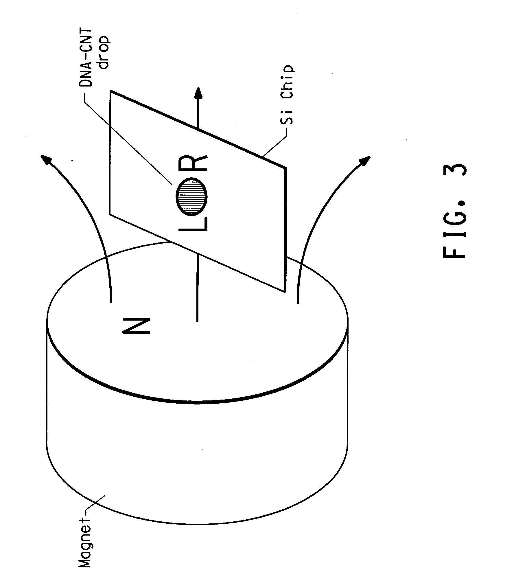
Deposition of DNA-CNT Solution on to Sio2 Surface
[0101] Silicon chips (about 1 cm×2 cm) with different thickness (100 to 500 nm) of thermal oxide layer on substrates of different crystal orientation and doping were used for this experiment.
[0102] Typically the center of a 1 cm×2 cm chip, a 2.5 mm×2.5 mm square was marked to define the location for solution deposition of the CNT's. Immediately before deposition, the SiO2 surface was scrubbed with Kimwipes® EX-L tissue (Kimberly-Clark, Roswell, Ga.) wetted with methanol. A 5 μL of DNA-CNT solution (2 μg / mL in water) was mixed with an equal volume of 20 mM Tris / 0.5 mM EDTA pH7 buffer, and then the entire 10 mL mixture was deposited onto the area defined by a marked square. After a 15 min incubation at room temperature, the surface was rinsed with pure water and blown dried with N2 gas.
example 3
CNT Alignment Observation by Atomic Force Microscopy
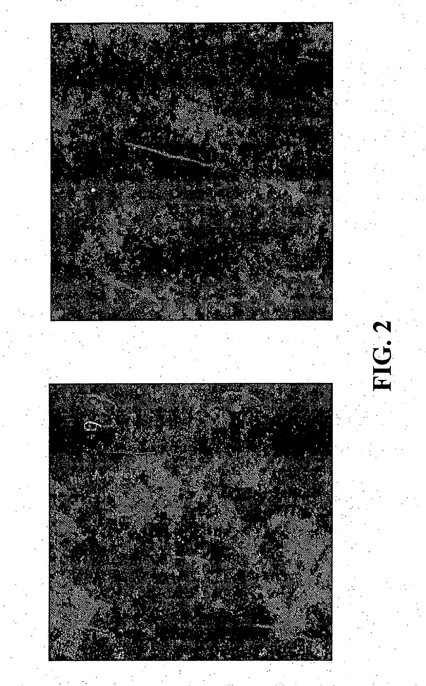
[0103] After deposition the alignment of the CNT's was observed using atomic force microscopy (AFM)
[0104] Tapping mode AFM was used to obtain height and phase imaging data simultaneously on a Nanoscope IIIa AFM, Dimension 3000 from Digital Instruments, (Santa Barbara, Calif.). Microfabricated cantilevers or silicon probes (Nanoprobes®, Digital Instruments) with 125 micron long cantilevers were used at their fundamental resonance frequencies which typically varied from 270-350 kHz depending on the cantilever. The cantilevers had a very small tip radius of 5-10 nm. The AFM was operated in ambient conditions with a double vibration isolation system. Extender electronics were used to obtain height and phase information simultaneously. AFM data were obtained in tapping mode, in air, using previously described methods. FIG. 1 shows the alignment orientation at two different spots on the chip for CNT's deposited as described in example ...
PUM
 Abstract
Description
Claims
Application Information