Process for the Production of Plasma Displays with Distributed Getter Material and Displays Thus Obtained

a technology of getter material and plasma display, which is applied in the manufacture of electrode systems, discharge tubes luminescnet screens, gas mixture absorption, etc., can solve the problems of deteriorating image quality, no longer being able to evacuate cells or fill, and water being regarded as the most dangerous impurity, etc., and achieves the effect of simple manufacturing process

Inactive Publication Date: 2008-01-24
SAES GETTERS SPA
View PDF12 Cites 3 Cited by
  • Summary
  • Abstract
  • Description
  • Claims
  • Application Information

AI Technical Summary

Benefits of technology

[0016] An object of the present invention is to overcome the shortcomings of the prior art, in particular to provide a simple manufacturing process for producing a plasma display panel containing a distributed getter.

Problems solved by technology

Recently, interfering effects between the electric discharges at contiguous pixels in one channel have been noticed (a phenomenon known as “cross-talking”), which cause a deterioration of the image quality, especially in the case of high-definition displays (i.e. having pixels of small dimensions).
It must be noted that while generally the choice of either process is free, in the particular case of displays with an internal structure with closed cells, as that shown in FIG. 5, it is necessary to resort to the chamber process, because after the sealing of the two glass panels it would no longer be possible to evacuate the cells or to fill them with the rare gas mixture via the tubulation.
In particular, among PDP manufacturers, water is the impurity regarded as the most dangerous one.
The first contribution is particularly important in the case of the pumping tabulation processes, in which the limiting factor for the evacuation speed of the inner space is the low gas conductance in the channels, which causes the problem that the removal of the impurities cannot be completed within the evacuation times (some hours) compatible with the industrial manufacturing processes of PDPs.
The problem is even worse in the case of PDPs with internal structures like those shown in FIGS. 3 and 4 (while as already stated, displays with a structure of type shown in FIG. 5 cannot be produced in this way).
In spite of the advantages offered, the getter systems according to these documents do not yet yield totally satisfactory results.
In fact, particularly during the service life of the display, the impurities need some time to reach the getter materials, during which inhomogeneity of gas composition across the PDP may arise, and consequently differences in luminosity or in image quality at different parts of the display.
However, in the structures described in these documents the getter deposits cover part of the surface dedicated to the light emission and thus an extremely precise control of dimensions and location of these deposits is required, with quite complex manufacturing processes.
These structures, however, show some constructive problems, in so far as the ribs are generally constructed by successive depositions of a suspension of particles of the desired material with the screen-printing technique, drying after every layer deposition, and final consolidation of the rib by thermal treatment.
The use of a mixture of various materials, among them a getter, gives some problems, since the getter could be contaminated during the thermal treatments of drying and consolidation by the vapors of the solvent used for the deposition, thus inactivating the getter for the service life of the display.
Conversely, the presence of getter particles could compromise the mutual adhesion of the particles of ceramic material of which the ribs are normally formed, thus reducing their mechanical resistance.
However, this solution also presents notable constructive difficulties.

Method used


Image

  • Process for the Production of Plasma Displays with Distributed Getter Material and Displays Thus Obtained
  • Process for the Production of Plasma Displays with Distributed Getter Material and Displays Thus Obtained
  • Process for the Production of Plasma Displays with Distributed Getter Material and Displays Thus Obtained

Examples


Embodiment Construction

[0026] The FIGS. 1 to 5 have been described in the Background section above.

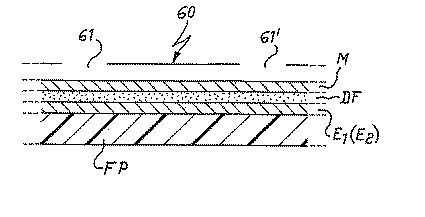
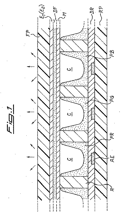
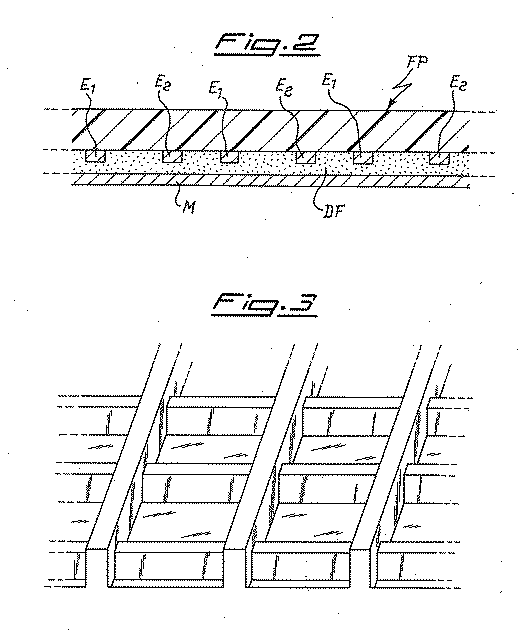
[0027] The process of the invention is different from the known processes only in that the manufacturing of the front glass panel comprises the steps of forming a number of getter deposits on the surface, that in the finished display is facing the inner space, at locations essentially corresponding to the contact areas with the upper portion of the ribs. The getter deposits may be formed either on the plane surface of the MgO layer (M in FIG. 1) or into recesses formed in this layer. The invention is applicable indifferently to either pumping tabulation or in chamber manufacturing processes of PDPs.

[0028]FIG. 6 shows the various steps of the operation characterizing the invention in a first embodiment (in this drawing, the front glass panel is shown upside down with respect to FIGS. 1-5). During step a, above the surface of the magnesium oxide layer onto which the getter deposits are to be formed, a mask 6...


PUM

PropertyMeasurementUnit
widthaaaaaaaaaa
widthaaaaaaaaaa
temperaturesaaaaaaaaaa

Abstract

A manufacturing process for the production of plasma display panels is provided which allows obtaining in a simple way displays in which getter materials deposits are present in contact with the atmosphere present in channels or cells of the display. The process includes a step of forming the getter material deposits on a free surface of the magnesium oxide layer at positions essentially corresponding to contact areas between the front glass panel and the barriers on the rear glass panel of the display panel.

Description

CROSS-REFERENCE TO RELATED APPLICATIONS [0001] This application is a section 371 of International Application No. PCT / IT2005 / 000385, filed on Jul. 6, 2005, which was published in the English language on Jan. 26, 2006, under International Publication No. WO 2006 / 008770 and the disclosure of which is incorporated herein by reference.BACKGROUND OF THE INVENTION [0002] The present invention relates to a process for manufacturing plasma display panels with distributed getter material; the invention relates also to the displays obtained according to the process of the invention. [0003] Plasma display panels are known under the abbreviation PDP, which will be used in the following. [0004] A PDP is composed of two planar glass parts, a front one and a rear one, sealed at their perimeter by a low-melting point glass paste. In this way, between the two glass parts a closed space is formed, filled with a rare gas mixture and comprising functional components, as specified in the following; gene...

Claims


Application Information

Patent Timeline
Patent Type & Authority Applications(United States)
IPC IPC(8): H01J9/26
CPCH01J9/385H01J2217/49264H01J9/40H01J9/39H01J11/52
Inventor LONGONI, GIORGIOCARRETTI, CORRADOTOMINETTI, STEFANO
Owner SAES GETTERS SPA
Why Eureka
Try Eureka