Controlling the synthesis gas composition of a steam methane reformer

a technology of steam methane reformer and synthesis gas composition, which is applied in the direction of liquid-gas reaction process, combustible gas production, combustible gas purification/modification, etc., can solve the problems of reducing the catalyst efficiency, serious environmental pollution, and a major dependence on petroleum, so as to improve the effect of economics

Inactive Publication Date: 2008-01-24
RGT UNIV OF CALIFORNIA
View PDF47 Cites 19 Cited by
  • Summary
  • Abstract
  • Description
  • Claims
  • Application Information

AI Technical Summary

Benefits of technology

[0018] This invention provides an improved, economical method to control the synthesis gas composition obtained from a steam methane reformer that obtains its feedstock as product gas direct

Problems solved by technology

Since the resources for the production of petroleum-based fuels are being depleted, dependency on petroleum will become a major problem unless non-petroleum alternative fuels, in particular clean-burning synthetic diesel fuels, are developed.
Moreover, normal combustion of petroleum-based fuels in conventional engines can cause serious environmental pollution unless strict methods of exhaust emission control are used.
A Fischer-Tropsch type process allows for the application of current state-of-art engine exhaust after-treatment methods for NOx reduction, removal of toxic particulates present in diesel engine exhaust, and the reduction of normal combustion product pollutants, currently accomplished by catalysts that are poisoned quickly by any sulfur prese

Method used


Image

  • Controlling the synthesis gas composition of a steam methane reformer
  • Controlling the synthesis gas composition of a steam methane reformer
  • Controlling the synthesis gas composition of a steam methane reformer

Examples


example 1

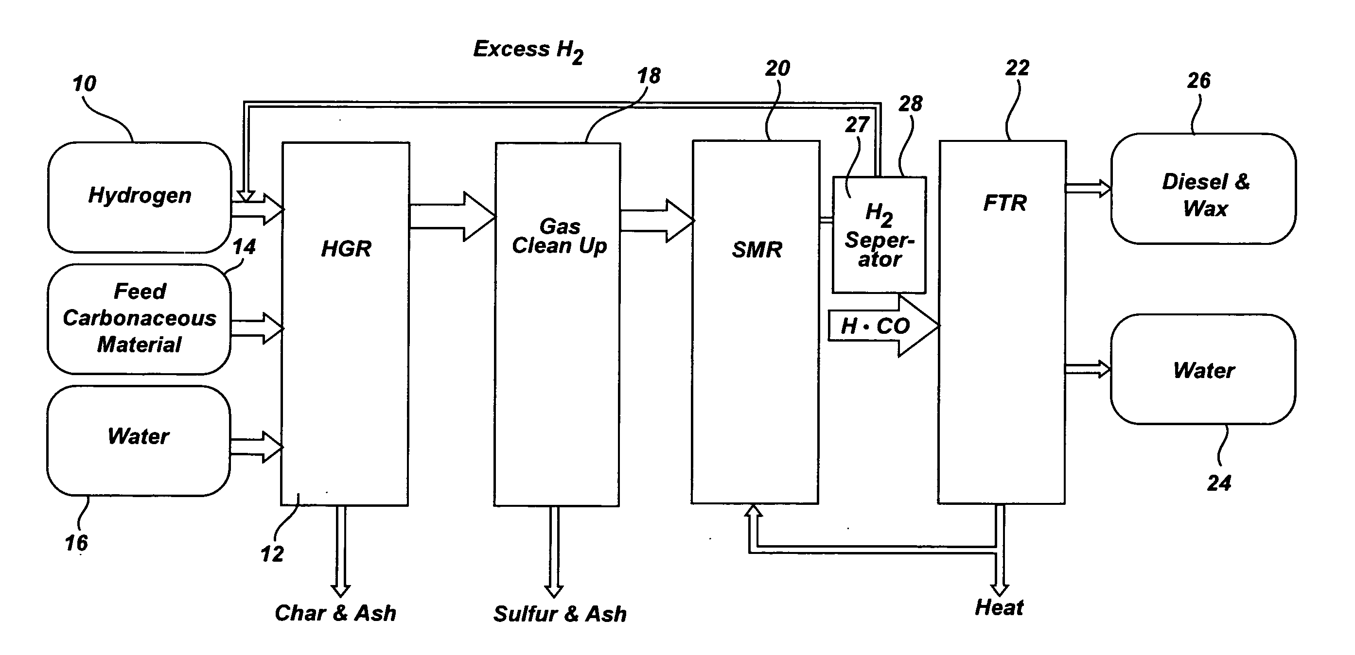
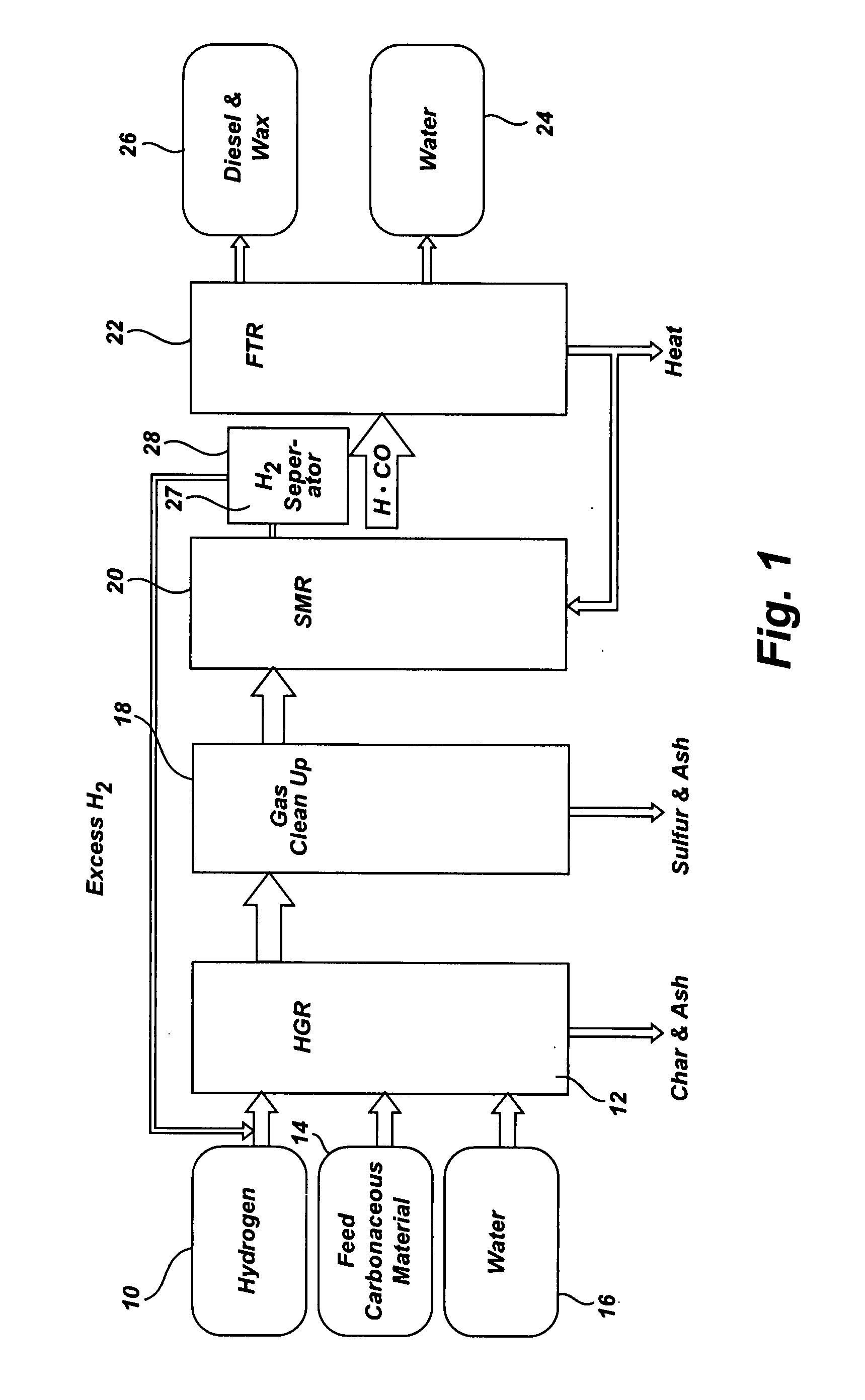
[0037]FIG. 1 is a flow diagram a SHR to SMR process one embodiment of the invention in which a desired H2 / CO ratio output of an SMR is, obtained by separating hydrogen from the SMR output, diverting it to the HGR, and adjusting the hydrogen feed and the water content of feedstock into the SHR that supplies the SMR. An internally generated hydrogen feed 10 is fed into an SHR 12 along with a carbonaceous feedstock 14 and water 16, which are heated to 750° C. at 400 psi in the SHR 12. The resulting producer gas is directed to a gas clean up filter 18, e.g. a candle filter assembly, at about 350° C. at about 400 psi. From there, after removal of sulfur and ash, the effluent is directed to an SMR 20 where synthesis gas is generated and fed to a Fischer-Tropsch type reactor 22, from which pure water 24, and diesel fuel and / or wax 26 is obtained. The SMR 20 output is passed through a hydrogen separator 27 where a portion of its hydrogen is separated and diverted from the SMR 20, at 28 to b...

example 2

[0042] This Example, shown in FIGS. 3-6, illustrates a second, preferred embodiment in which a portion of the output of the SMR is itself recycled. FIG. 3 is flow diagram of the SHR to SMR process in which a desired H2 / CO ratio output of an SMR is obtained by without separating hydrogen from the SMR output, but diverting a portion of the SMR output itself to the HGR, and adjusting the hydrogen feed and the water content of feedstock into the SHR that supplies the SMR. The process is the same as described in Example 1 but for those changes reflecting the direct use of a portion of the SMR as feed to the SHR. Accordingly, while some hydrogen is used to start the process, as shown in FIG. 4, discussed below, internally generated hydrogen feed is that component of the SMR output, as shown at 10a in FIG. 3. As in Example 1, the SMR portion 10a is fed into an SHR 12 along with a carbonaceous feedstock 14 and water 16, which are heated to 750° C. at 400 psi in the SHR 12. The resulting pro...


PUM

PropertyMeasurementUnit
Temperatureaaaaaaaaaa
Pressureaaaaaaaaaa

Abstract

A method for controlling the synthesis gas composition obtained from a steam methane reformer (SMR) that obtains its feedstock as product gas directly from a steam hydro-gasification reactor SHR). The method allows control of the H2/CO syngas ratio by adjusting the hydrogen feed and the water content of feedstock into a steam hydro-gasification reactor that supplies the SMR. The steam and methane rich product gas of the SHR is generated by means of hydro-gasification of a slurry of carbonaceous material and water. The mass percentages of the product stream at each stage of the process are calculated using a modeling program, such as the ASPEN PLUS™ equilibrium process. By varying the parameters of solid to water ratio and hydrogen to carbon ratio, a sensitivity analysis can be performed that enables one determine the optimum composition of the slurry feedstock to the SHR to obtain a desired syngas ratio output of the SMR. Thus one can adjust the hydrogen feed and the water content of feedstock into the SHR that supplies the SMR to determine the syngas ratio output of the SMR.

Description

CROSS-REFERENCE TO RELATED APPLICATIONS [0001] This application is a continuation-in-part of, and claims the benefit of, patent application Ser. No. 11 / 489,298, filed Jul. 18, 2006.FIELD OF THE INVENTION [0002] The field of the invention is the production of synthesis gas. BACKGROUND OF THE INVENTION [0003] There is a need to identify new sources of chemical energy and methods for its conversion into alternative transportation fuels, driven by many concerns including environmental, health, safety issues, and the inevitable future scarcity of petroleum-based fuel supplies. The number of internal combustion engine fueled vehicles worldwide continues to grow, particularly in the midrange of developing countries. The worldwide vehicle population outside the U.S., which mainly uses diesel fuel, is growing faster than inside the U.S. This situation may change as more fuel-efficient vehicles, using hybrid and / or diesel engine technologies, are introduced to reduce both fuel consumption and...

Claims


Application Information

Patent Timeline
IPC IPC(8): C07C27/00
CPCC01B3/38C10G2300/807C01B2203/04C01B2203/062C01B2203/0805C01B2203/1241C01B2203/1258C01B2203/127C01B2203/148C01B2203/84C10G2/30C10J3/00C10J2300/0916C10J2300/0946C10J2300/0966C10J2300/0973C10J2300/1659C10J2300/1807Y02E20/18Y02E50/32C10K1/024C10K1/143C10K1/16C10K1/165C10G2300/1003C10G2300/1011C10G2300/42C01B2203/0233Y02P20/145Y02P30/20Y02E50/30
Inventor NORBECK, JOSEPH M.PARK, CHAN SEUNGRAJU, ARUN SK
Owner RGT UNIV OF CALIFORNIA
Why Eureka
Try Eureka