Optical sensor utilizing hollow-core photonic bandgap fiber with low phase thermal constant

Active Publication Date: 2008-02-07
THE BOARD OF TRUSTEES OF THE LELAND STANFORD JUNIOR UNIV
View PDF22 Cites 33 Cited by
  • Summary
  • Abstract
  • Description
  • Claims
  • Application Information

AI Technical Summary

Benefits of technology

[0074] Since some of the mode energy resides in the holes including the core of the photonic-bandgap fiber and some of mode energy resides in the solid portions of the fiber (typically a silica-based glass), the Kerr effect in a photonic-bandgap fiber (PBF) includes two contributions. One contribution is from the solid portions of the fiber, and one contribution is from the holes. The residual Kerr constant of a photonic-bandgap fiber, n2,PBF, can be expressed as the sum of these two contributions according to the following equation:
[0075] In certain embodiments, the parameter ηnl is equal to Aeff/Aeff, silica, where Aeff and Aeff, silica are the mode effective area and mode effective area in silica, respectively. These quantities can be computed as follows: Aeff=1ng2⁣(∫∫Waveguidecross-section⁢ɛr⁡(x,y)⁢E⁡(x,y)2⁢ⅆx⁢ⅆy)2∫∫Waveguidecross-section⁢E⁡(x,y)4⁢ⅆx⁢ⅆyAeff,silica=1ng2⁣(∫∫Waveguidecross-section⁢ɛr⁡(x,y)⁢E⁡(x,y)2⁢ⅆx⁢ⅆy)2∫∫silica⁢E⁡(x,y)4⁢ⅆx⁢ⅆy
[0076] For standard silica fiber, the percentage of the optical mode contained in the cladding is generally in the range of 10% to 20%. In the hollow-core photonic-bandgap fiber 13, the percentage of the optical mode in the cladding 114 is estimated to be about 1% or substantially less. Accordingly, in the photonic-bandgap fiber 13, the effective nonlinearity due to the solid portions of the fiber may be decreased by a factor of approximately 20. According to this estimate, by using the hollow-core photonic-bandgap fiber 13, the Kerr effect can be reduced by at least one order of magnitude, and can be reduced much more with suitable design. Indeed, measurements indicate that the photonic-bandgap fibers can be designed with a parameter ηnl small enough that the Kerr constant of the solid portion of the fiber, n2.solid, is negligible compared to the hole contribution, n2.holes(1−ηnl). Even in the case where n2.solid is much larger than n2.holes, the fiber can be designed in such a way that ηnl is sufficiently small that n2.holes(1−ηnl) is larger than n2.solidηnl. See, for example, D. G. Ouzounov et al., Dispersion and nonlinear propagation in air-core photonic-bandgap fibers, Proceedings of the Conf. on Lasers and Electro-optics, Paper CThV5, June 2003.
[00

Problems solved by technology

The method further comprises optically interfering the first and second portions of the light signal after the first and secon

Method used


Image

  • Optical sensor utilizing hollow-core photonic bandgap fiber with low phase thermal constant
  • Optical sensor utilizing hollow-core photonic bandgap fiber with low phase thermal constant
  • Optical sensor utilizing hollow-core photonic bandgap fiber with low phase thermal constant

Examples


example 1

[0112] This example describes the operation of an air-core photonic-bandgap fiber gyroscope in accordance with certain embodiments described herein. Because the optical mode in the sensing coil travels largely through air in an air-core photonic-bandgap fiber, which has much smaller Kerr, Faraday, and thermal constants than silica, the air-core photonic-bandgap fiber has far lower dependencies on power, magnetic field, and temperature fluctuations. With a 235-meter-long fiber coil, a minimum detectable rotation rate of about 2.7° / hour and a long-term stability of about 2° / hour were observed, consistent with the Rayleigh backscattering coefficient of the fiber and comparable to what is measured with a conventional fiber. Furthermore, the Kerr effect, the Faraday effect, and Rayleigh backcattering can be reduced by a factor of about 100-500, and the Shupe effect by a factor of about 3-11, depending on the fiber design.

[0113] We confirm some of these predictions with the demonstration...

example 2

[0131] This example models quantitatively the dependence of the fundamental-mode phase on temperature in an air-core fiber, and validates these predictions by comparing them to values measured in actual air-core fibers. The metric cited in this example is the relative change in phase S, referred to as the phase thermal constant, and given by Equation (4): S=1ϕ⁢ⅆϕⅆT(4)

where φ is the phase accumulated by the fundamental mode through the fiber and T is the fiber temperature. With an interferometric technique, two air-core PBFs from different manufacturers were tested and found that their thermal constant is in the range of 1.5 to 3.2 parts per million (ppm) per degree Celsius, or 2.5-5.2 times lower than the measured value of a conventional SMF28 fiber (S=7.9 ppm / ° C.). Each of these values falls within 20% of the corresponding predicted number, which lends credence to the theoretical model and to the measurement calibration. This study shows that the reason for this reduction is due...

example 3

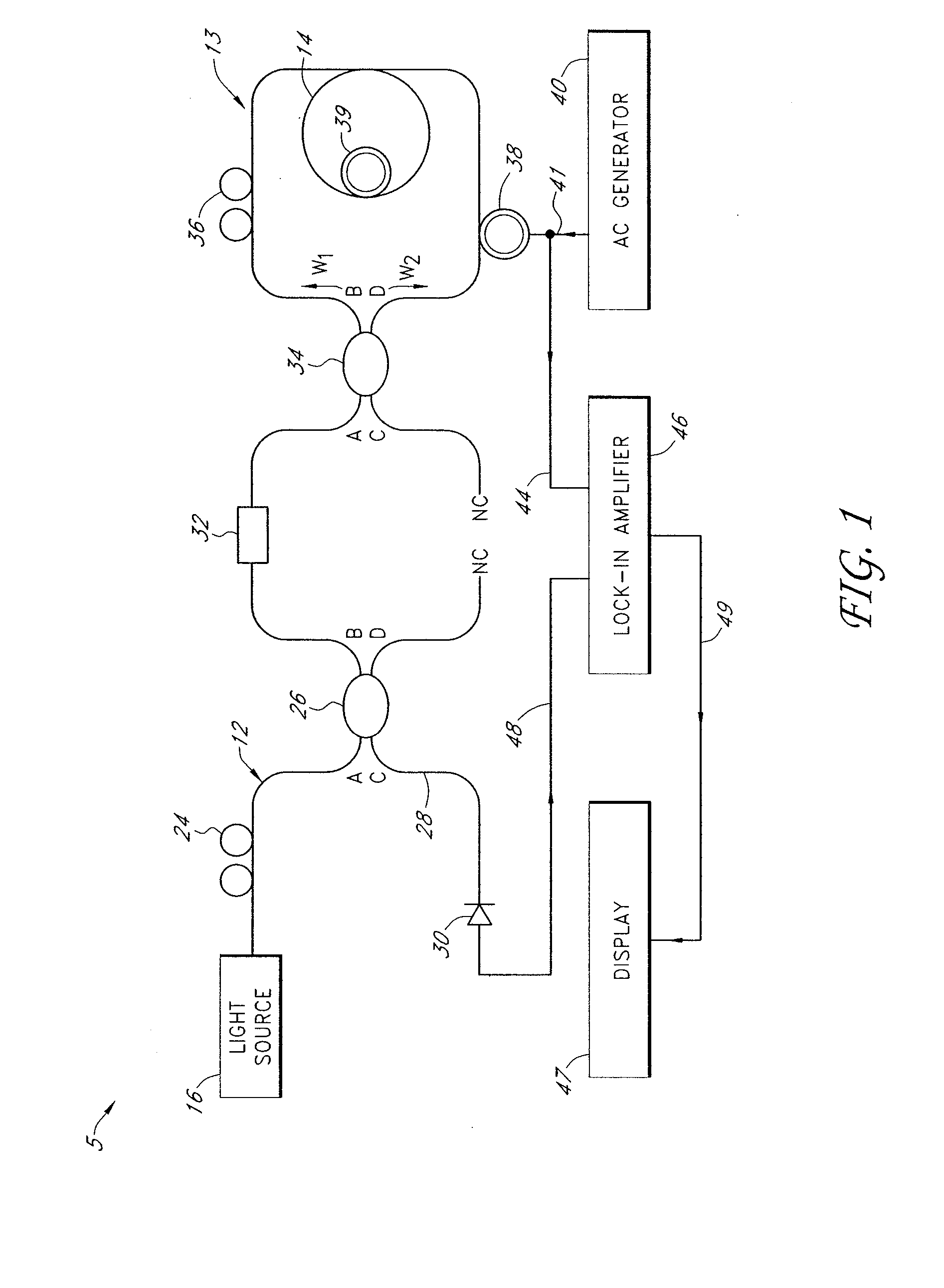
[0162]FIG. 20 schematically illustrates an example configuration for testing a fiber optic gyroscope 905 compatible with certain embodiments described herein. The sensing coil 910 comprises a Blaze Photonics air-core fiber having a length of 235 meters wound in 16 layers on an 8-centimeter-diameter spool using quadrupole winding to reduce the thermal and acoustic sensitivities of the coil 910. Each fiber layer in the coil 910 was bonded to the layer underneath it with a thin epoxy coating, and the outermost layer was also coated with epoxy. This fiber was essentially single-moded at the signal wavelength of about 1.54 microns (the few higher order modes were very lossy). The calculated scale factor of this coil 910 was 0.255 s. Light from a broadband Er-doped superfluorescent fiber source (SFS) 920 was isolated by isolator 922, transmitted through a polarization controller (PC1) 924, and split by a 3-dB fiber coupler before being coupled to a fiber-pigtailed LiNbO3 integrated optica...


PUM


Abstract

An optical sensor includes a directional coupler comprising at least a first port, a second port, and a third port. The first port is in optical communication with the second port and with the third port such that a first optical signal received by the first port is split into a second optical signal that propagates to the second port and a third optical signal that propagates to the third port. The optical sensor further includes a photonic bandgap fiber having a hollow core and an inner cladding generally surrounding the core. The photonic bandgap fiber is in optical communication with the second port and with the third port. The second optical signal and the third optical signal counterpropagate through the photonic bandgap fiber and return to the third port and the second port, respectively. The photonic bandgap fiber has a phase thermal constant S less than 8 parts-per-million per degree Celsius.

Description

CLAIM OF PRIORITY [0001] This application claims benefit under 35 U.S.C. §119(e) to U.S. Provisional Patent Application No. 60 / 817,514, filed Jun. 29, 2006 and U.S. Provisional Patent Application No. 60 / 837,891, filed Aug. 14, 2006, each of which is incorporated in its entirety by reference herein.BACKGROUND OF THE INVENTION [0002] 1. Field of the Invention [0003] The present invention relates to fiber optic sensors, and more particularly, relates to fiber optic interferometers for sensing, for example, rotation, movement, pressure, or other stimuli. [0004] 2. Description of the Related Art [0005] A fiber optic Sagnac interferometer is an example of a fiber optic sensor that typically comprises a loop of optical fiber to which lightwaves are coupled for propagation around the loop in opposite directions. After traversing the loop, the counterpropagating waves are combined so that they coherently interfere to form an optical output signal. The intensity of this optical output signal ...

Claims


Application Information

Patent Timeline
IPC IPC(8): G01B9/02
CPCG01C19/721G02B6/02328G01D5/3538G01D5/35322
Inventor DIGONNET, MICHEL J.F.KIM, HYANG KYUNBLIN, STEPHANEDANGUI, VINAYAKKINO, GORDON S.
Owner THE BOARD OF TRUSTEES OF THE LELAND STANFORD JUNIOR UNIV
Why Eureka
Try Eureka