

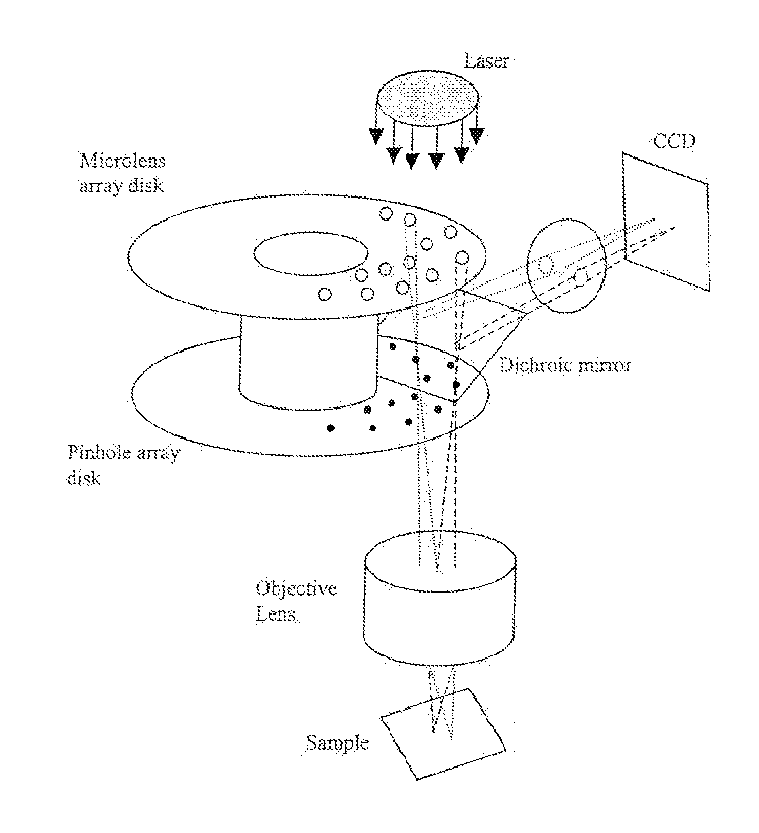
Laser confocal scanning microscope and methods of improving image quality in such microscope
a laser confocal scanning microscope and microscope technology, applied in the field methods of improving image quality in such microscopes, can solve the problems of reducing the overall efficiency of the system by half, random striping, and complicating the production of such configurations, so as to reduce the appearance of stripe, reduce the variation in illumination intensity distribution, and increase the intensity throughput of laser confocal scanning microscopes
- Summary
- Abstract
- Description
- Claims
- Application Information
AI Technical Summary
Benefits of technology
Problems solved by technology
Method used
Image

Examples
first embodiment
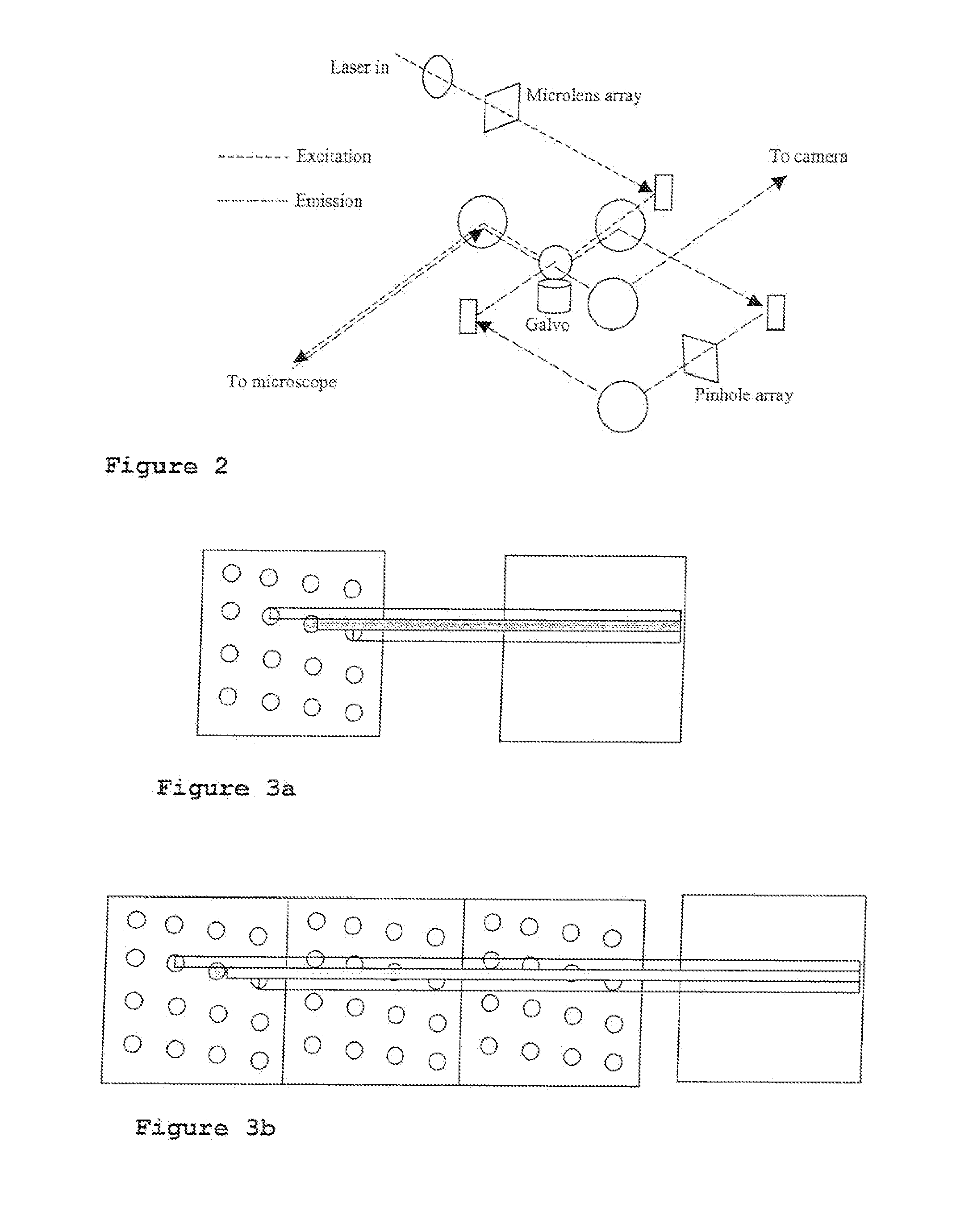
[0034]A first embodiment to overcome the lower throughput efficiency and to reduce the random ‘striping’ due to imperfections in the microlens or aperture arrays of the 2-D array laser confocal scanner design requires additional scan patterns to be incorporated into the microlens array and scanned by the galvanometer mirror. These additional repeat patterns along the axis of the scanning direction permit the scanning process to scan across the sample without the ‘dead’ time inherent in the original design. The patterns are arranged such that the patterns at each end of the array are fully superimposed over the field of view when the galvanometer mirror changes its scan direction. Thus it becomes possible to continuously illuminate the sample during the scanning process, without ‘dead’ time (compare FIG. 4 and FIG. 5a).
[0035]With continuous illumination of the field of view, the detected intensity during the slowing, stationary and accelerating stages of the change of scan direction ...
second embodiment
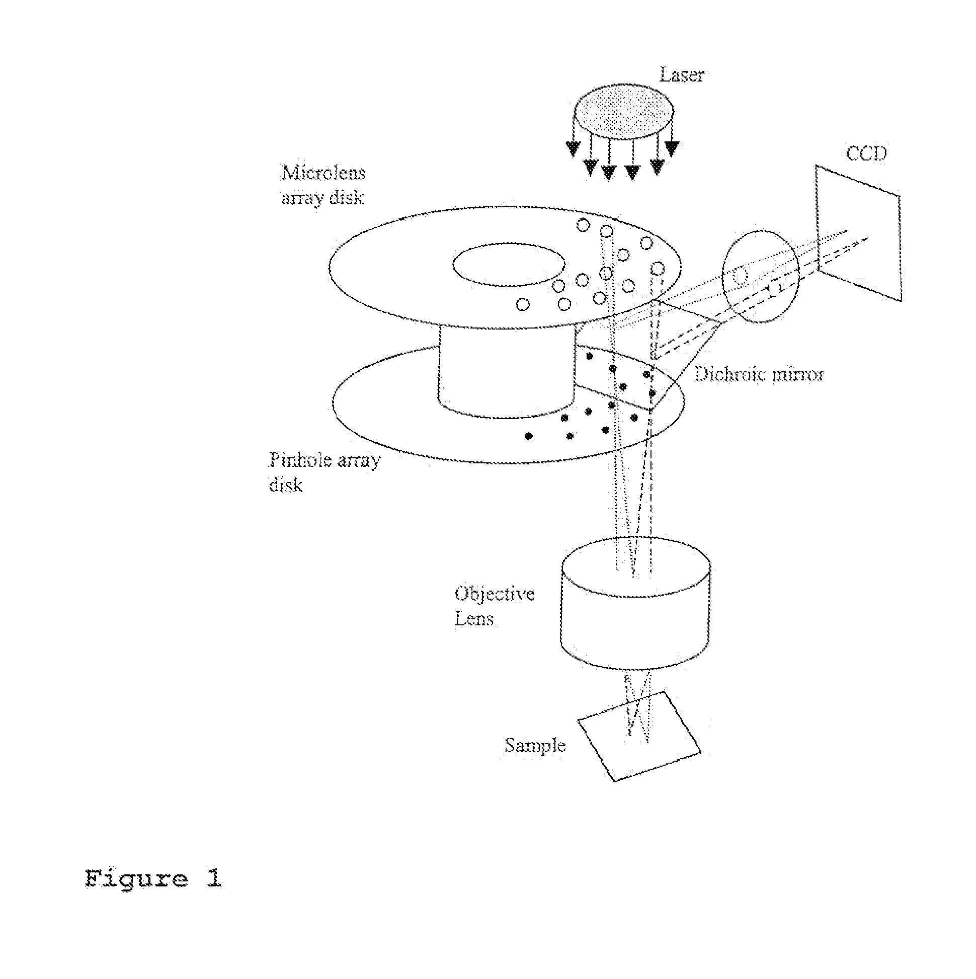
[0037]In a second embodiment the coherency effects that give rise to a regular pattern of ‘striping’ in the detected images due to the scanning of the illumination source intensity distribution across the image (sample) with the scanning of the microlens generated points across the image is eliminated. The introduction of a second galvanometer mirror into the illumination path (FIG. 5c), between the laser Illuminator output and the input side of the microlens array, such that it is perfectly synchronised with the first galvanometer mirror and that the rotation of the second galvanometer mirror is arranged to descan the illumination source, causing the illumination source to remain stationary at the scanned image (sample) plane (FIG. 5b) while the microlens generated spots continue to be scanned over the image (sample). This reduces the appearance of the pattern of ‘striping’ in the detected images.
[0038]A third alternative embodiment for curing the coherency artefact is to reduce th...
sixth embodiment
[0041]A sixth embodiment adapts the selectable size confocal aperture array to use air in place of oil (optical fluid) between the fixed and moving plates and is designed to maintain a small constant separation between the plates. Sliding the moving plate along one axis permits a selected aperture from an array of different sized apertures to he aligned with the aperture in the fixed plate. The fixed and sliding aperture plates are mounted so as to be recessed below the surface of their respective plate carriers, thus the surfaces of the aperture plates are prevented from rubbing against each other, thus eliminating a potential cause of damage.
PUM
 Abstract
Description
Claims
Application Information