Optical Scanning Device

a scanning device and optical technology, applied in the field of optical scanning devices, can solve the problems of mechanical tolerance, deterioration of the efficiency of evanescent coupling, and deviation from the desired tilt alignment, and achieve the effect of accurate and efficient scanning of record carriers

Inactive Publication Date: 2008-02-14
KONINKLIJKE PHILIPS ELECTRONICS NV
View PDF4 Cites 35 Cited by
  • Summary
  • Abstract
  • Description
  • Claims
  • Application Information

AI Technical Summary

Benefits of technology

[0009]It is an object of the invention to provide an optical scanning device for accurately and efficiently scanning record carriers using e

Problems solved by technology

For near-field systems using evanescent coupling to scan record carriers, a deviation from a desired level of tilt alignment has a detrimental effect on the quality and accuracy of data being written and/or read during scanning of the record carrier.
Near-field systems employing evanescent coupling have relatively small margins of mechanical tolerance, outside of which the efficienc

Method used


Image

  • Optical Scanning Device
  • Optical Scanning Device
  • Optical Scanning Device

Examples


Embodiment Construction

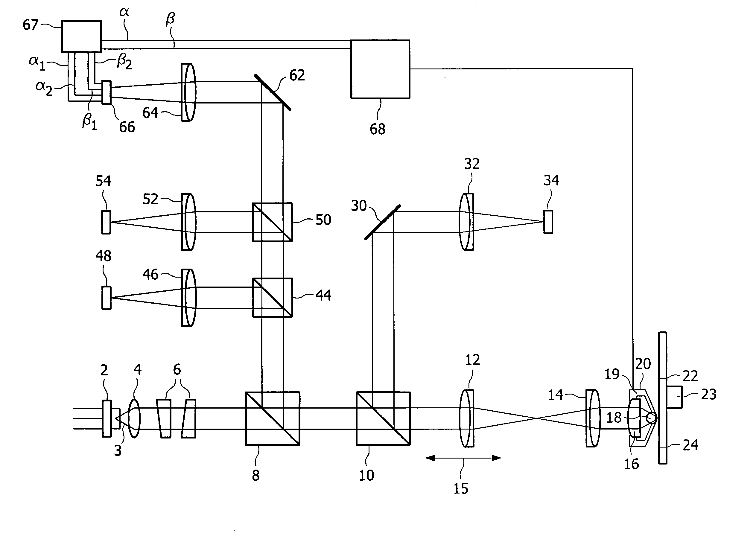
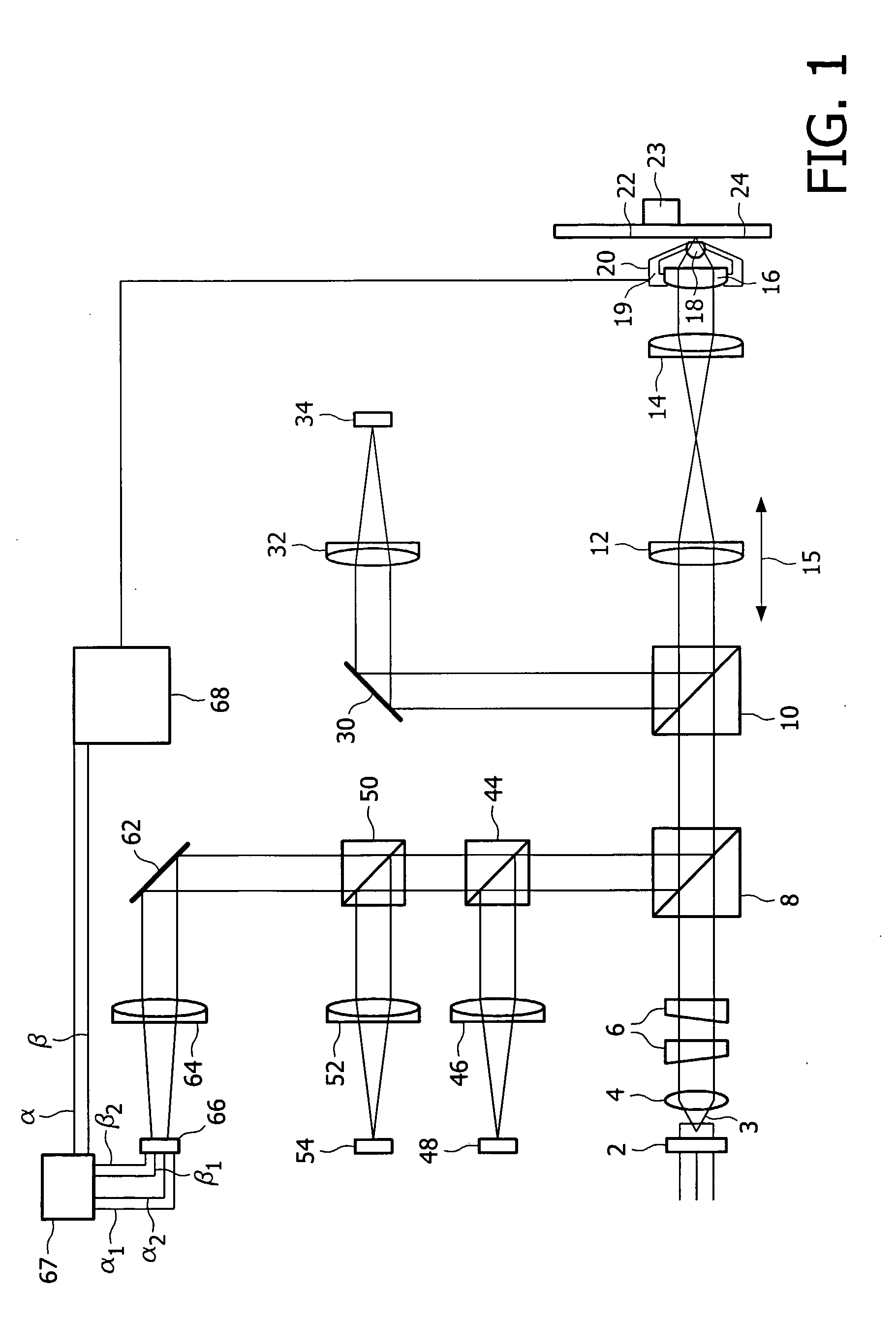
[0040]FIG. 1 shows schematically an optical scanning device for scanning a record carrier in accordance with an embodiment of the present invention.

[0041]The optical scanning device comprises a radiation source system which is arranged to generate a radiation beam. In this embodiment the radiation source system is a laser 2 and the radiation beam is a laser beam 3 having a predetermined wavelength λ, for example approximately 405 nm. During both a start-up procedure and a record carrier scanning procedure of the optical scanning device, the radiation beam 3 passing along an optical axis OA of the optical scanning device (not indicated) is collimated by a collimator lens 4 and its cross-sectional intensity distribution shaped by a beam shaper 6. The radiation beam 3 then passes through a non-polarising beam splitter 8, followed by a polarising beam splitter 10 and is then focused by a first focus adjustment lens 12 and a second focus adjustment lens 14. The focusing of the radiation ...


PUM


Abstract

An optical scanning device for scanning a record carrier (22), the record carrier has an outer face (24) and the optical scanning device comprises a radiation source system (2) arranged to generate a radiation beam; an objective system (20) having an exit face (76) and which is arranged between the radiation source system and the record carrier and provides for evanescent coupling of the radiation across a gap between the exit face of the objective system and the outer face of the record carrier; and a radiation detector arrangement for detecting radiation after interaction with the record carrier. The radiation detector arrangement is arranged to produce a tilt error signals (α, β) representing a tilt misalignment between the exit face of the objective system and the outer face of the record carrier. The radiation detector arrangement is arranged to produce the tilt error signal by detecting information in the radiation which is indicative of a variation in efficiency off the evanescent coupling across the exit face.

Description

FIELD OF THE INVENTION[0001]The present invention relates to an optical scanning device for scanning record carriers, in particular for scanning record carriers using evanescent coupling of radiation.BACKGROUND OF THE INVENTION[0002]In a particular type of high-density optical scanning device, a solid immersion lens (SIL) is used to focus a radiation beam to a scanning spot onto an information layer of a record carrier. A certain distance between the exit face of the SIL and the outer face of the record carrier, for example 25 nm, is desirable to allow evanescent coupling of the radiation beam from the SIL to the record carrier. Evanescent coupling may otherwise be referred to as frustrated total internal reflection (FTIR). Such systems are known as near-field systems, deriving their name from the near field formed by the evanescent wave at an exit face of the SIL. An exemplary optical scanning device may use a radiation source which is a blue laser and emits a radiation beam having...

Claims


Application Information

Patent Timeline
IPC IPC(8): G11B7/135
CPCG11B7/0956G11B2007/13727G11B7/1387G11B7/085G11B7/09G11B7/095
Inventor VERSCHUREN, COEN ADRIANUSZIJP, FERRY
Owner KONINKLIJKE PHILIPS ELECTRONICS NV
Why Eureka
Try Eureka