Method and apparatus for improving light load efficiency in switching power supplies

Active Publication Date: 2008-02-21
INFINEON TECH AMERICAS CORP
View PDF11 Cites 41 Cited by
  • Summary
  • Abstract
  • Description
  • Claims
  • Application Information

AI Technical Summary

Benefits of technology

[0008] It is an object of the present invention to provide

Problems solved by technology

The disadvantages of this control are: variable frequency control for all input and load condition; instead of the average output voltage, the minimum output voltage is regulated to reference; the control is affected by the comparator delay; reliance on a reasonably large equivalent series resistance (ESR) of the output capacitor to generate the output voltage ramp for off-tim

Method used


Image

  • Method and apparatus for improving light load efficiency in switching power supplies
  • Method and apparatus for improving light load efficiency in switching power supplies
  • Method and apparatus for improving light load efficiency in switching power supplies

Examples


Embodiment Construction

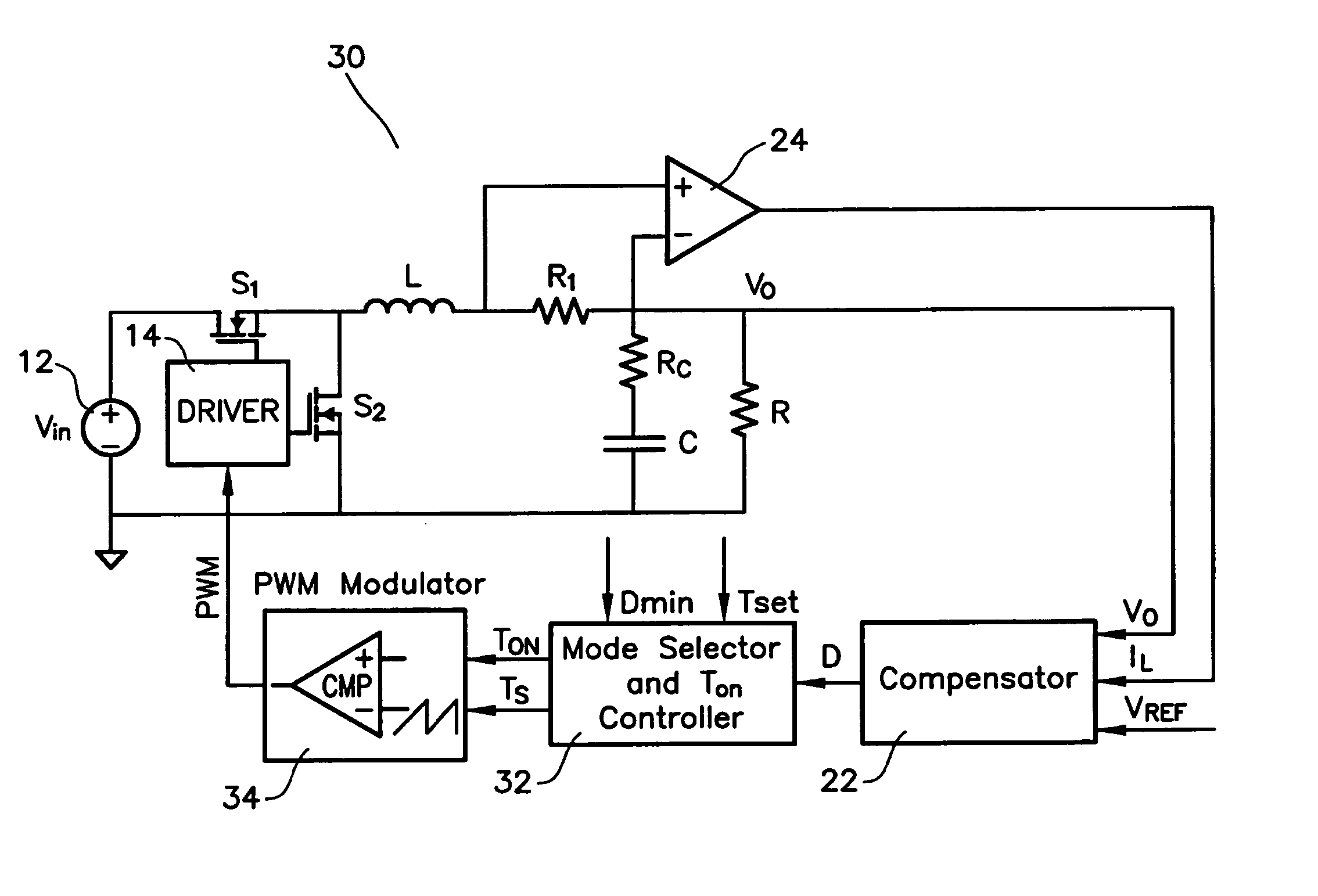
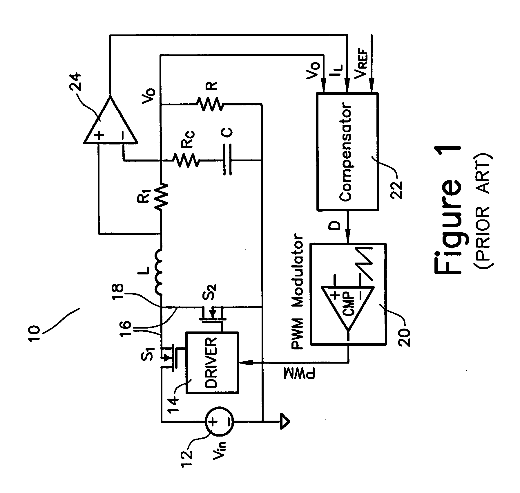
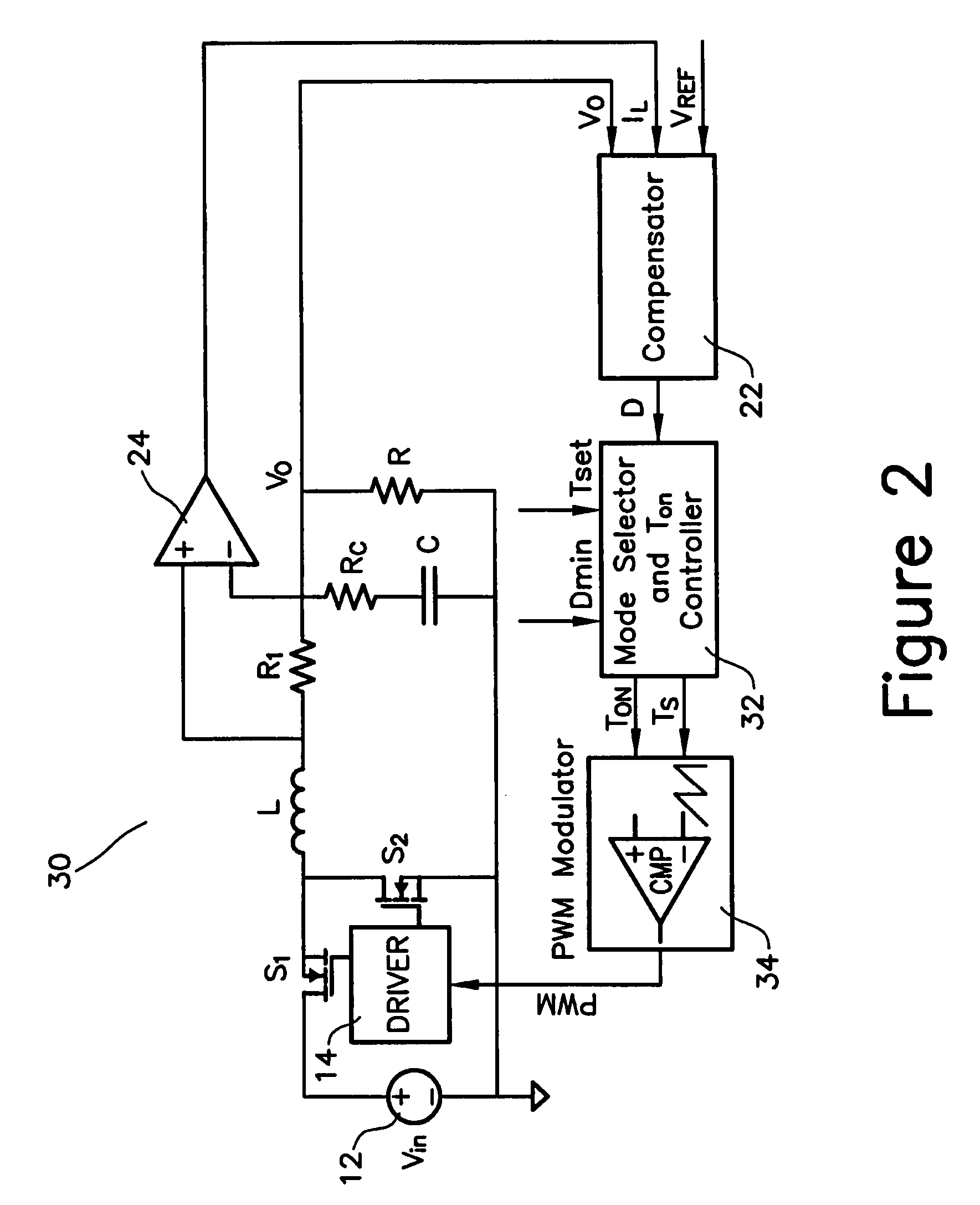
[0017] In FIG. 1 a synchronous buck converter is used for illustrative purposes. However, the same principle may be applied to other topologies, as well. In FIG. 1 circuit 10 includes a driver 14 connected to gate terminals of a half-bridge stage 16 having transistors S1 and S2 connected at a common node 18. Second terminals of the transistors S1 and S2 being connected to a source 12. The driver 14 controlling the half-bridge stage 16 in accordance with PWM signals received from a PWM modulator 20. The PWM signals are based on a computed duty cycle value D provided by a compensator 22.

[0018] A load L is connected to the common node 18 and series connected to a resistor R1. The resistor R1 is connected at a second node to a resistor RC that is series coupled to a capacitor C and to a resistor R. An amplifier 24 receives its positive input from the connection between the load L and the resistor R1 and the negative input from the second node. The compensator 22 receives a predefined r...


PUM


Abstract

A circuit for transitioning between a discontinuous and a fixed frequency continuous conduction mode (DCM) and (CCM) of a power converter having a driver receiving PWM signals and controlling a switching stage comprises a control switch and a sync switch connected at a common switching node for driving a load. The circuit including a PWM modulator for providing PWM signals; and a mode selector for receiving a duty cycle value, a preset switching period, and a duty cycle at a critical conduction point having a switching frequency equal to the preset switching period and providing an on-time of the control switch and a switching period to the PWM modulator, wherein if the duty cycle value is greater than the duty cycle at a critical conduction point, the PWM modulator will drive will provide the PWM signals to operate the switching stage in the CCM with constant-frequency duty cycle control, and if the duty cycle value is less than duty cycle at a critical conduction point, the PWM modulator will drive will provide the PWM signals to operate the switching stage in the DCM by turning off the sync switch when a load current becomes negative.

Description

CROSS-REFERENCE TO RELATED APPLICATIONS [0001] This application is based on and claims priority to U.S. Provisional Patent Application Ser. No. 60 / 797,766, filed on May 4, 2006 and entitled METHOD AND APPARATUS FOR IMPROVING LIGHT LOAD EFFICIENCY IN SWITCHING POWER SUPPLIES, the entire contents of which are incorporated by reference herein.BACKGROUND OF THE INVENTION [0002] The present invention relates to light-load efficiency of power converters, and more particularly to smooth transition between heavy- and light-loads of power converters. [0003] Light-load efficiency of power converters is becoming increasingly important for switch mode power supply (SMPS) powered devices. Improved light-load efficiency helps save energy and extend battery life of the SMPS powered devices. Conventional methods for improving the light-load efficiency of the power converters include: reducing the circulation energy and associated losses by running a power converter's circuit in a discontinuous cond...

Claims


Application Information

Patent Timeline
IPC IPC(8): H03K3/017
CPCH02M3/156Y02B70/16H02M2001/0032H02M1/0032Y02B70/10
Inventor CHEN, RENGANGBROWN, JAMES
Owner INFINEON TECH AMERICAS CORP
Why Eureka
Try Eureka