Method of determining laser stabilities of optical materials, crystals selected according to said method, and uses of said selected crystals

a technology of optical materials and laser stability, which is applied in the direction of material analysis, instruments, spectrum investigation, etc., can solve the problems of loss of optical quality, change in imaging behavior, and change of lens geometry

Active Publication Date: 2008-02-21
HELLMA MATERIALS
View PDF10 Cites 5 Cited by
  • Summary
  • Abstract
  • Description
  • Claims
  • Application Information

AI Technical Summary

Benefits of technology

[0012]It is an object of the present invention to provide an improved evaluation method, with which laser-stable and especially laser-stabile materials can be identified or determined and especially with which samples of laser-stable and especially laser-stable material can be differentiated or distinguished from each other with regard to their laser stability.
[0013]It is another object of the present invention to provide an improved evaluation method for determining the laser stability of materials and for distinguishing laser-stable materials from each other that can be performed in a shorter time than currently available or prior art evaluation methods.

Problems solved by technology

While the intrinsic absorption is independent of the respective quality of the material, the additional non-intrinsic components of the absorption lead to a loss of quality of the optical material.
This sort of heating of the optical material has the disadvantage that the optical properties, such as the index of refraction, change, which leads to a change in the imaging behavior in an optical component used to beam formation, since the index of refraction not only depends on the wavelength of the light but also on the temperature of the optical material.
Moreover heating of an optical component leads to a change of the lens geometry.
This leads especially in photolithography, such as is used for making computer chips and electronic circuits, to a quality impairment or to an increase in the number of rejects.
That is clearly undesirable.
However so that these sorts of measurements were possible, crystals with a relatively high impurity level were used, which are insufficient for the high requirements of photolithography.
It has now been shown that the fluorescence values so obtained may not be used for quality control or for determination of the extent of impurity formation and thus for formation of color centers in crystals of high quality.
Since manufacture of an entire optical component from an optical blank is very expensive and labor-intensive, there is already a need to establish the extent and nature or the radiation damage that would arise in the optical component during later usage at an earlier time point, i.e. prior to working the blank.
Unsuitable material must be discarded.
This requirement results from the productivity requirements of this sort of apparatus, which may well increase because of increases in laser power and thus inherent increases of the energy density.
The sensitivity of the aforementioned short-time measuring method for pre-evaluation of suitable optical raw material is thus no longer sufficient in order to distinguish samples with especially good laser-stability from other laser-stable samples.

Method used


Image

  • Method of determining laser stabilities of optical materials, crystals selected according to said method, and uses of said selected crystals
  • Method of determining laser stabilities of optical materials, crystals selected according to said method, and uses of said selected crystals
  • Method of determining laser stabilities of optical materials, crystals selected according to said method, and uses of said selected crystals

Examples


example 1

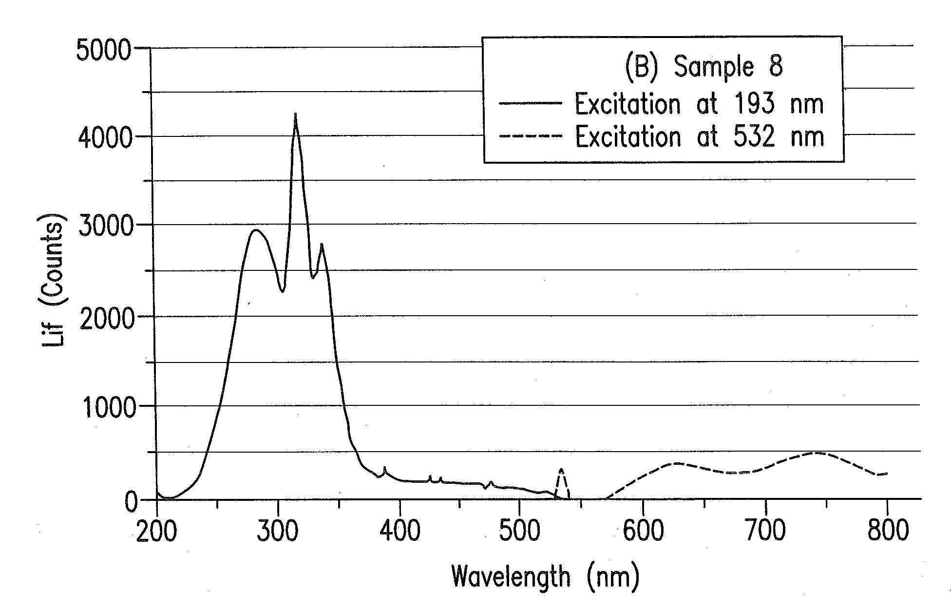
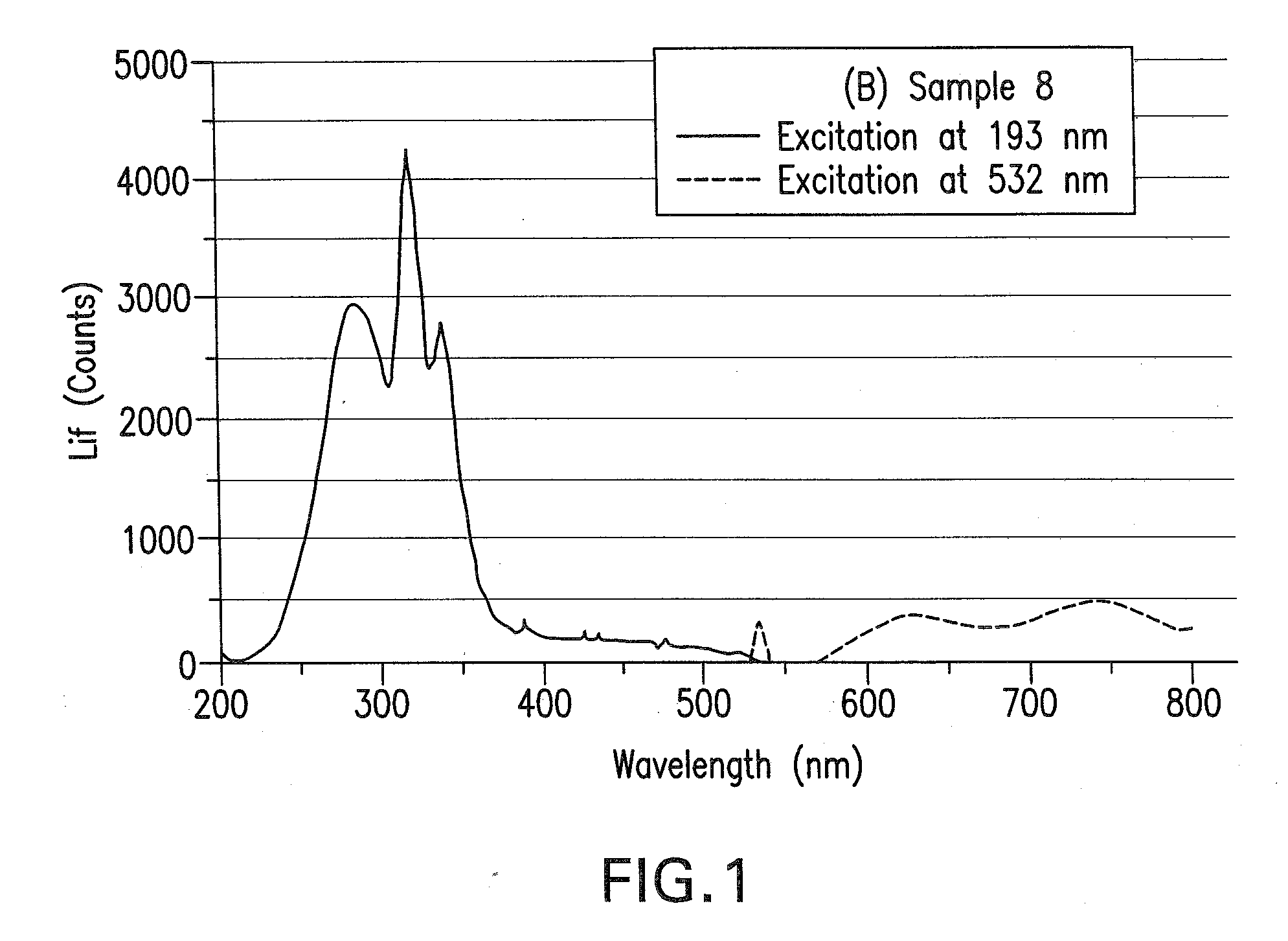
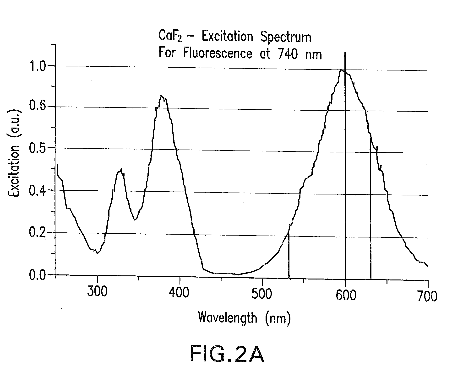
[0050]A 3 cm×3 cm sample was broken off of a polycrystalline ingot made from melted calcium fluoride powder. This crystal sample was irradiated in a holder with about 10,000 pulses (3 min at 60 Hz) of light with an energy density of 30 mJ / cm2 from an ArF excimer laser. Subsequently immediately after pre-irradiation and after a waiting time of 20 minutes the sample was irradiated with light at 532 nm (GLIF) and the intensities of the fluorescence at a wavelength of 740 nm were measured by means of a CCD camera (Spectrometer system with CCD camera as detector). The measurement occurred by means of a CCD camera as described in the already mentioned WO 2004 / 027395. The normalized value of Z is calculated according to the above-described equation 1:

Z=(I2,λ1,λ2−I1,λ1,λ2) / I2,λ1,λ2  (1).

The following measured fluorescence intensities of the fluorescence at 740 nm were obtained by excitation with wavelengths λ1a of 532 nm or λ1b of 635 nm for the different CaF2 samples no. 1 to 5. The result...

example 2

[0052]A previously obtained CaF2 crystal was pre-irradiated with 10,000 laser pulses from an ArF laser at a repetition rate of 60 Hz with an energy density of 10 mJ / cm2. Subsequently this sample was irradiated with a green solid state laser with a wavelength of 532 nm and fluorescence intensities were measured immediately after pre-irradiation and also after 15, 10, 20, 30, and 45 minutes. The intensities of the fluorescence were measured at wavelengths of 630 nm and 740 nm. The results are illustrated in the appended FIGS. 3A and 3B.

[0053]While the invention has been illustrated and described as embodied in a method of determining the laser stability of optical materials, crystals selected according to the method, and uses of the selected crystals, it is not intended to be limited to the details shown, since various modifications and changes may be made without departing in any way from the spirit of the present invention.


PUM

PropertyMeasurementUnit
wavelengthsaaaaaaaaaa
wavelength rangeaaaaaaaaaa

Abstract

The method determines laser stability of an optical material, which is suitable for making an optical element through which high-energy light passes. The method includes pre-irradiation to produce radiation damage and measurement of the resulting induced non-intrinsic fluorescence. The method is distinguished by excitation of induced fluorescence immediately after pre-irradiation and after at least ten minutes after pre-irradiation with light of a wavelength between 350 and 810 nm, and measurement and quantitative evaluation of fluorescence intensities at wavelengths between 550 nm and 810 nm. Especially laser-stable optical materials, particularly CaF2 crystals, have a normalized difference (Z) of the fluorescence intensities measured at a first time immediately after pre-irradiation and at a second time at least ten minutes after the pre-irradiation, as calculated by the following equation (1):Z=(I2,λ1,λ2−I1,λ1,λ2)I2,λ1,λ2,   (1)which is less than 0.3.

Description

CROSS-REFERENCE[0001]German Patent Application DE 10 2006 038 902.6, filed Aug. 18, 2006 in Germany, describes substantially the same invention as described herein below and claimed in the claims appended herein below and provides the basis for a claim of priority for the instant invention under 35 U.S.C. 119 (a)-(d). The disclosure in the foregoing German Patent Application DE 10 2006 038 902.6 is hereby incorporated herein by explicit reference thereto.BACKGROUND OF THE INVENTION[0002]1. Field of the Invention[0003]The present invention relates to a method of evaluating suitable optical material for making optical elements for high-energy radiation and to the use of the optical materials obtained by this method.[0004]2. Description of the Related Art[0005]It is known that materials from which optical elements are made absorb more or less of the light or radiation that passes through them, so that the intensity of the light and / or the radiation is generally less after passing throu...

Claims


Application Information

Patent Timeline
Patent Type & Authority Applications(United States)
IPC IPC(8): G01N1/00
CPCG01N21/6402
Inventor NATURA, UTEKEUTEL, DIETMARPARTHIER, LUTZENGEL, AXEL
Owner HELLMA MATERIALS
Why Eureka
Try Eureka