Optical Compensation Layer-Attached Polarizing Plate, Liquid Crystal Panel, Liquid Crystal Display, Image Display, and Method for Producing Optical Compensation Layer-Attached Polarizing Plate
a technology of optical compensation layer and polarizing plate, which is applied in the direction of optics, polarising elements, instruments, etc., can solve the problems of unevenness or irregularities, large overall thickness of optical compensation layer attached polarizing plate, and easy to occur unevenness or irregularities, so as to reduce the number of processes in the lamination of optical compensation layers and improve productivity. , the effect of reducing the thickness
- Summary
- Abstract
- Description
- Claims
- Application Information
AI Technical Summary
Benefits of technology
Problems solved by technology
Method used
Image
Examples
example 1
Polarizing Plate
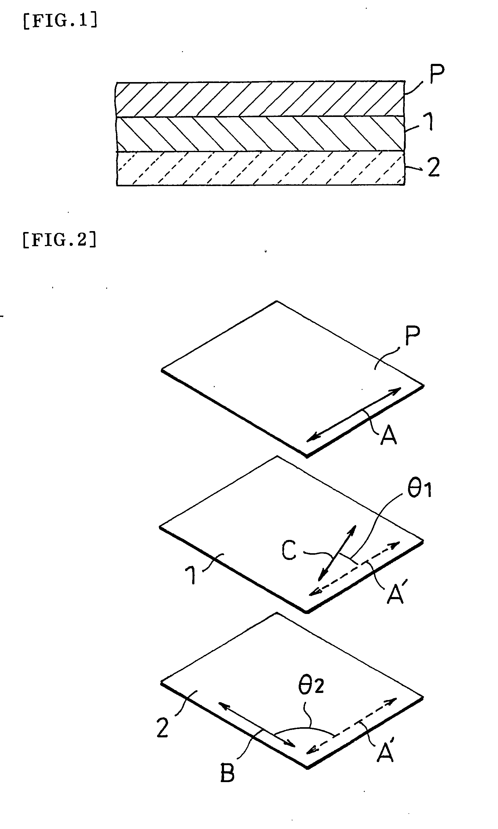
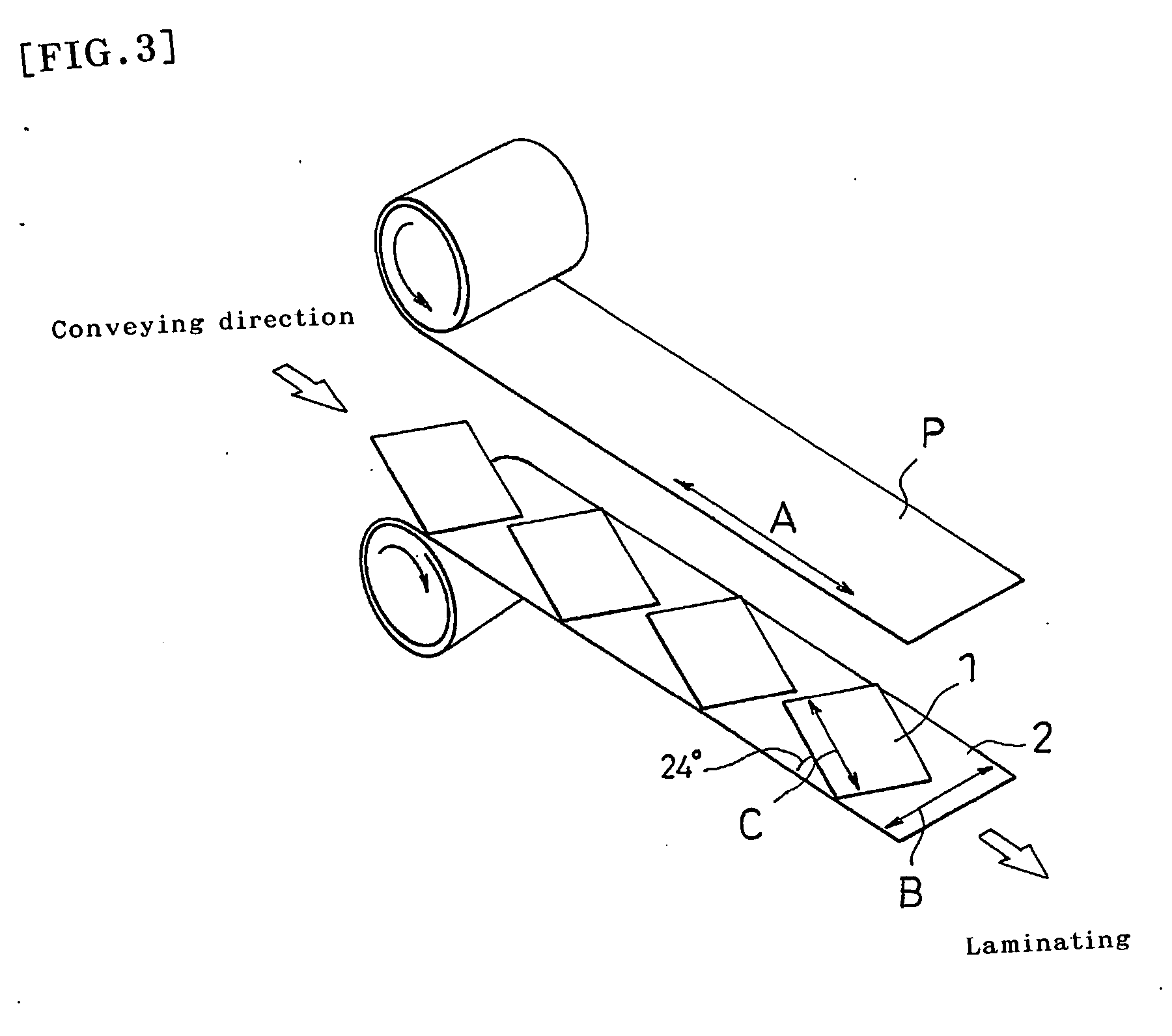
[0106] A polyvinyl alcohol film (VF-PS manufactured by Kuraray Co., Ltd.) was stretched at a stretch ratio of about 6 in an aqueous solution containing iodine and potassium iodide and then dried to form a 30 μm-thick belt-shaped polarizer. A triacetyl cellulose film (25 μm in thickness) manufactured by Fuji Photo Film Co., Ltd. (serving as a belt-shaped protective film) was bonded to each of both sides of the polarizer with a polyvinyl alcohol adhesive so that an about 100 μm-thick belt-shaped polarizing plate (1300 mm in width) was prepared. In addition, an acrylic pressure-sensitive adhesive layer (20 μm in thickness) for adhering to the optical compensation layer (1) and a separator were sequentially formed on one side of the polarizing plate, having the protective film on the other side.
(Optical Compensation Layer (1))
[0107] An about 60 μm-thick belt-shaped film made of a norbornene resin with a photoelastic coefficient absolute value of 3.1×10⁻¹² (m2 / N) was ...
example 2
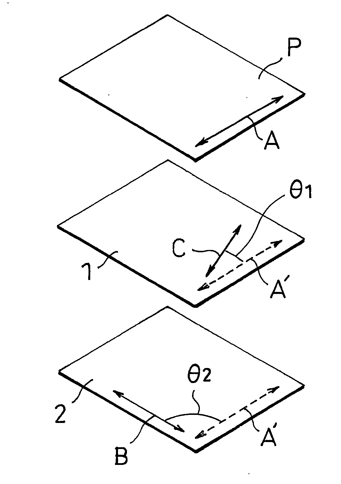
[0127] An optical compensation layer-attached polarizing plate was prepared using the process of Example 1, except that the optical compensation layer (1) was interposed between the polarizing plate (P) and the optical compensation layer (2) in such a manner that the slow axis C of the optical compensation layer (1) made an angle of 10° with the absorption axis A of the polarizing plate (P).
example 3
[0128] An optical compensation layer-attached polarizing plate was prepared using the process of Example 1, except that the optical compensation layer (1) was interposed between the polarizing plate (P) and the optical compensation layer (2) in such a manner that the slow axis C of the optical compensation layer (1) made an angle of 14° with the absorption axis A of the polarizing plate (P).
PUM
 Abstract
Description
Claims
Application Information
 - R&D
- Intellectual Property
- Life Sciences
- Materials
- Tech Scout
- Unparalleled Data Quality
- Higher Quality Content
- 60% Fewer Hallucinations
Browse by: Latest US Patents, China's latest patents, Technical Efficacy Thesaurus, Application Domain, Technology Topic, Popular Technical Reports.
© 2025 PatSnap. All rights reserved.Legal|Privacy policy|Modern Slavery Act Transparency Statement|Sitemap|About US| Contact US: help@patsnap.com


