Brushless motor driving device, brushless motor starting method, and method of detecting rotor stop position of brushless motor

Inactive Publication Date: 2008-02-28
MITSUBA CORP
View PDF2 Cites 112 Cited by
  • Summary
  • Abstract
  • Description
  • Claims
  • Application Information

AI Technical Summary

Benefits of technology

[0049]In accordance with the present invention, it is possible to detect induced voltage generated at the motor terminals without being influenced by pulse width modulation signals or the like by making a coasting state during starting. Because of this, it is possible to accurately detect rotor position without being influenced by disturbances. Also, because rotor position is detected during the coasting, it is possible to detect rotor position in a sh

Problems solved by technology

However, when the rotational frequency is zero or the rotational frequency is extremely low, such as during startup of a brushless motor, since the induced voltage is not generated or is extremely small, a signal sufficient for detection of the rotational position is not acquired.
However, when detecting the stop position of a rotor, in the method as disclosed in Japanese Unexamined Patent Application, First Publication No. 2004-40943, it is necessary to add transistors, resistors, and comparators and the like that constitute a stop position detecting circuit that detects the rotor stop position, thus becoming a factor in complicating the device constitution.
Also, as the difference between voltage rise times is small, the inductance difference becomes minute, thereby hindering an accurate determination.
The method disclosed in Japanese Unexamined Patent Application, First Publication No. 2002-335691 has the advantage of eliminating special-purpose circuits, but since the difference between inductances due to the impressed voltage in the three-phase energization is small, the difference between pulse widths of square-wave pulse voltages becomes small, thereby hindering an accurate detection.
Also, among conventional methods of starting a brushless mo

Method used


Image

  • Brushless motor driving device, brushless motor starting method, and method of detecting rotor stop position of brushless motor
  • Brushless motor driving device, brushless motor starting method, and method of detecting rotor stop position of brushless motor
  • Brushless motor driving device, brushless motor starting method, and method of detecting rotor stop position of brushless motor

Examples


first embodiment

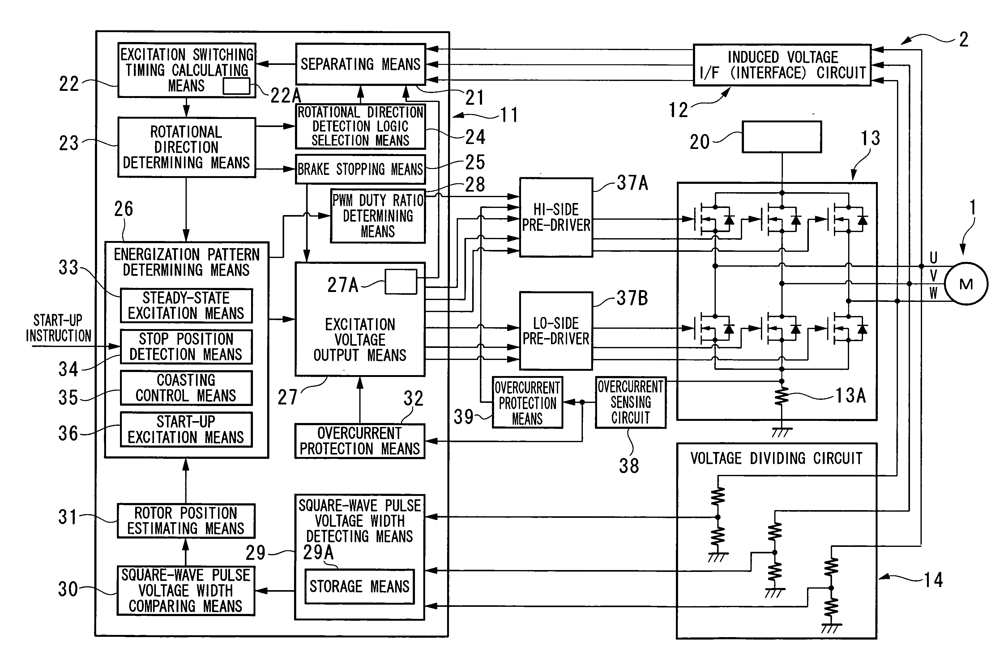
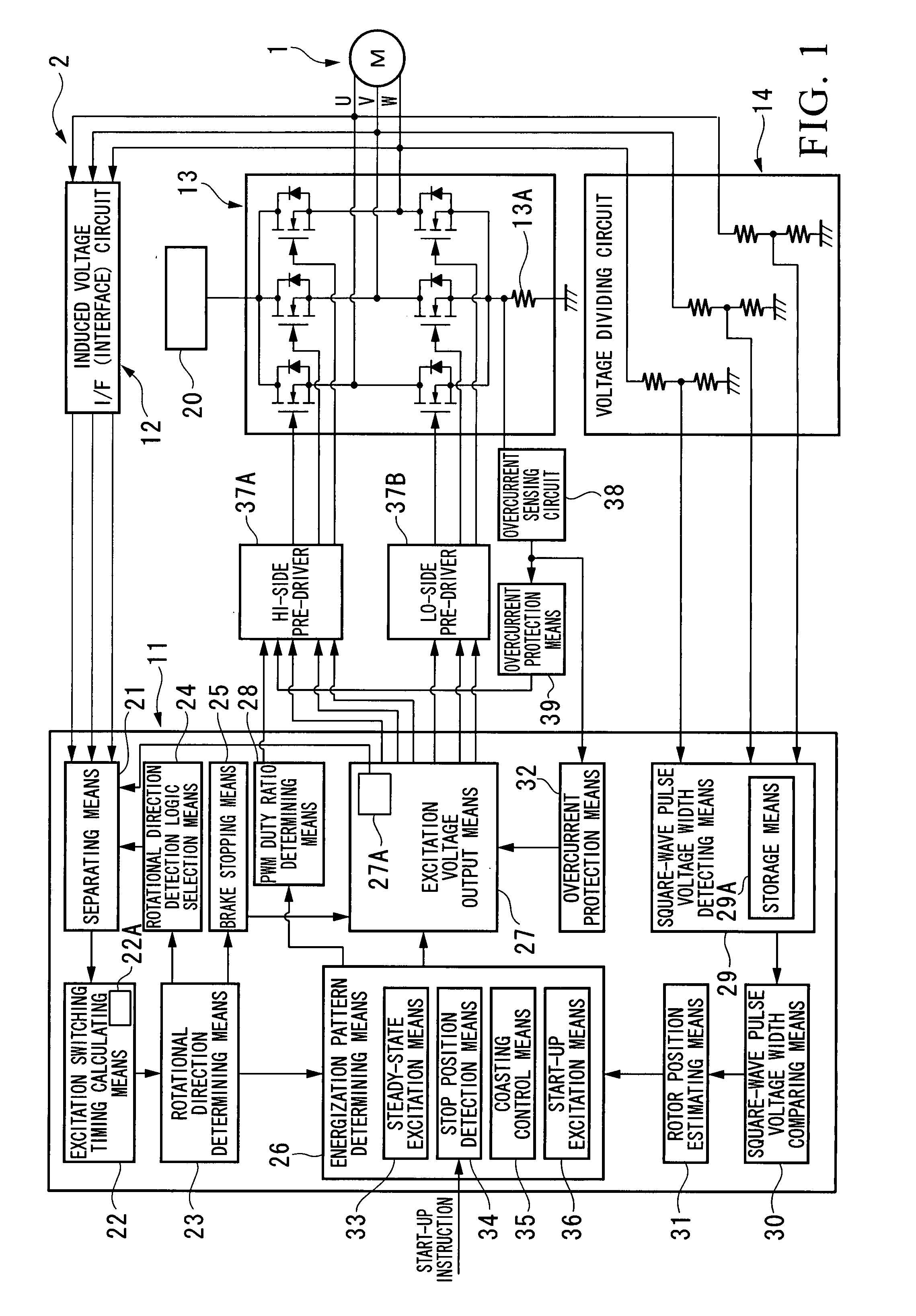
[0074]As shown in FIG. 1, a brushless motor system has a brushless motor 1 and a driving device 2 that controls the rotational driving of the brushless motor 1.

[0075]The brushless motor 1 has a rotor that has permanent magnet and a stator. In the stator, coils of three phases (U, V, W) are wound in that order in the circumferential direction. This brushless motor system is a sensor-less type system that does not have a sensor that detects the rotor position.

[0076]The driving device 2 has a control unit 11 which is formed of microcomputers and the like, an induced voltage I / F (interface) circuit 12 that detects the voltage that is impressed on the current-carrying wires that form the coils of three phases of the brushless motor 1, an inverter 13, and a voltage dividing circuit 14 that is a level conversion circuit that converts the level of the voltage that is impressed on the current-carrying wires of the brushless motor 1, in which pre-drivers 37A and 37B, an overcurrent sensing ci...

second embodiment

[0181]This embodiment uses reverse rotation specific logic in addition to forward rotation specific logic. The constitution of the apparatus is identical to that of the first embodiment.

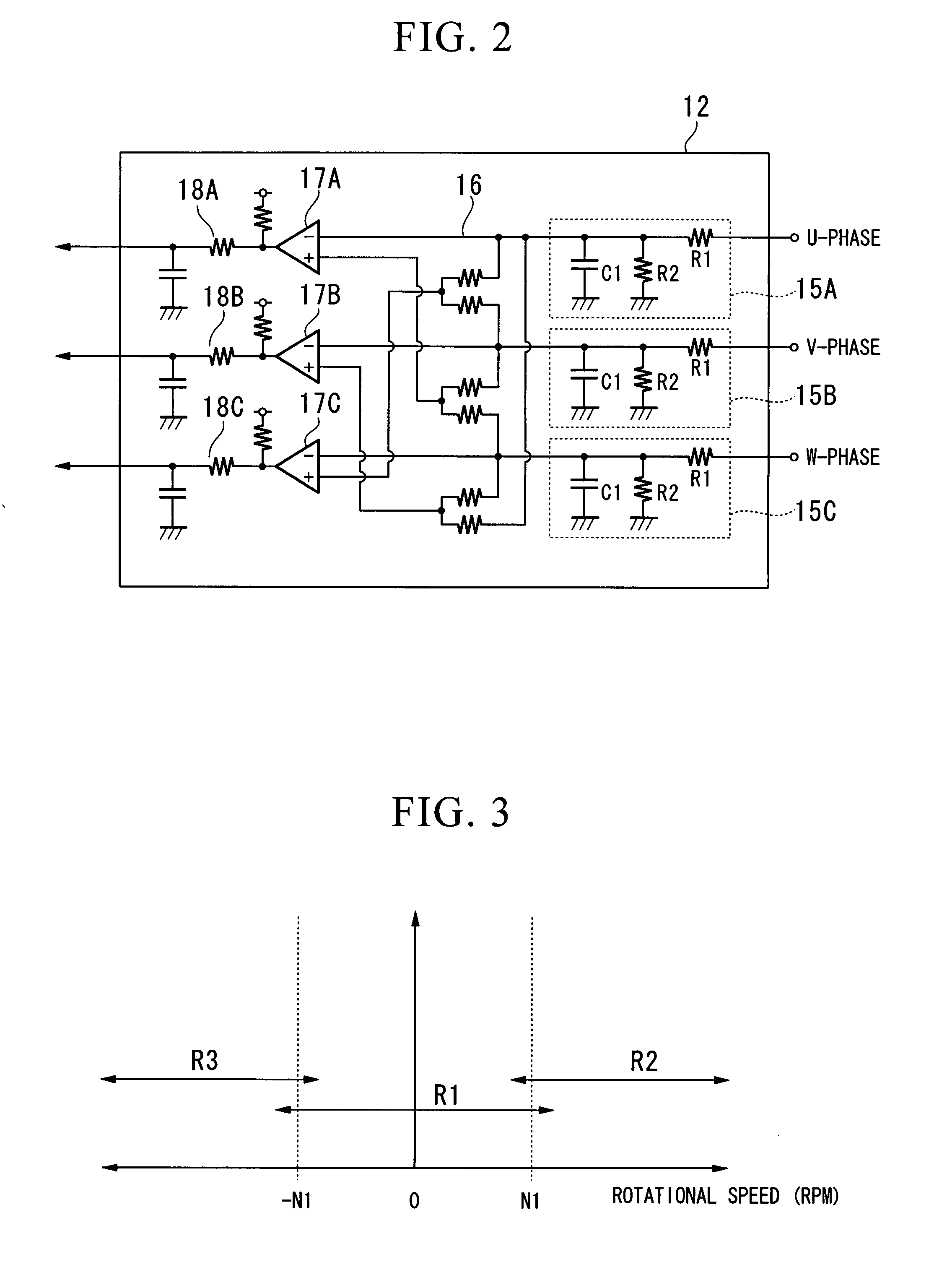
[0182]FIG. 19 is a flowchart of operation during start-up. In the flowchart, the processing from step S101 to step S108, that is, the processing when the rotational speed of the brushless motor 1 during start-up initiation is in region R1 or region R2 of FIG. 3, is identical to the first embodiment. When the rotational speed during start-up is in region R3, the processing proceeds from step S108 to step S110A.

[0183]In step S110A, the rotor position is detected by detecting the induced voltage using the reverse rotation specific logic. The reverse rotation specific logic is selected by the rotational direction detection logic selection device 24 in the case of the rotational direction determining device 23 determining that the brushless motor 1 is rotating in reverse. The reverse rotation specific log...

third embodiment

[0187]This embodiment initially performs a brake process.

[0188]As shown in FIG. 20, after the overflow current detection process is performed (step S101), a two-phase energization lock process is performed at a low duty ratio (step S102A). The brake time is a prescribed time (step S102B). These processes are processes that correspond to steps S111 and S112 in the first embodiment. During start-up, even when the rotational speed of the brushless motor 1 is in any of regions R1 to R3; it is forcibly controlled to region R1 by the brake process. The subsequent processes are the same as the first embodiment.

[0189]Also, as shown in FIG. 21, even when using the reverse rotation specific logic (corresponding step S110A), by initially performing a brake process in steps S102A and S102B, even when the rotational speed of the brushless motor 1 is in any of regions R1 to R3, the rotational speed is forcibly controlled to region R1 by the brake process.

[0190]While preferred embodiments of the i...


PUM


Abstract

When starting a brushless motor, if the stop position of the rotor is detected between time t1 and time t2, a start-up excitation pattern in accordance with the rotor stop position is input for an initial energization time Ts1. Afterward, when the energization is stopped, a plurality of signals SL1, SL2, SL3, SL4 are generated in sequence in excitation switch timing signals in accordance with the rotational position of the coasting rotor. From these signals SL1 to SL4, the rotor position is detected using the second and subsequent signals SL2 to SL4 and then the process shifts to ordinary energization switch control. In accordance with the present invention, it is possible to start up a motor in a short time with a simple method so as to obtain a large torque during start-up.

Description

BACKGROUND OF THE INVENTION[0001]1. Field of the Invention[0002]The present invention relates to a brushless motor driving device, a brushless motor starting method, and a method of detecting the rotor stop position of a brushless motor.[0003]Priority is claimed on Japanese Patent Application No. 2006-206390, filed Jul. 28, 2006, Japanese Patent Application No. 2006-242647, filed Sep. 7, 2006, and Japanese Patent Application No. 2007-000469, filed Jan. 5, 2007, the content of which is incorporated herein by reference.[0004]2. Description of Related Art[0005]In a brushless motor of the type in which the rotor has a permanent magnet, position sensorless drive control may be performed in which position sensors that detect the rotational position of the rotor are not provided. In this case, the rotational position of the rotor is detected from the edge gap of a pulse signal obtained by inputting an induced voltage that appears at the motor terminals of an open section (non-energized pha...

Claims


Application Information

Patent Timeline
IPC IPC(8): H02P6/18H02P6/20H02P6/06H02P6/08H02P6/182H02P6/185H02P6/21
CPCH02P6/185F04D27/004H02P6/22H02P6/205F05D2260/85H02P6/21Y02B30/70
Inventor SHIBUYA, SHINJI
Owner MITSUBA CORP
Why Eureka
Try Eureka