
Methods and systems for reducing tensile residual stresses in compressed tubing and metal tubing products produced from same

a technology of compressed tubing and compressed tubing, which is applied in the direction of mechanical equipment, engine components, other domestic articles, etc., can solve the problems of affecting the quality of welds, and reducing the mechanical properties of the material, so as to reduce the stress state of compressed ends, reduce the loss of mechanical strength, and reduce the stress state of tensile residual stress

Active Publication Date: 2008-03-06
ARCONIC TECH LLC
View PDF10 Cites 6 Cited by
  • Summary
  • Abstract
  • Description
  • Claims
  • Application Information

AI Technical Summary

Benefits of technology

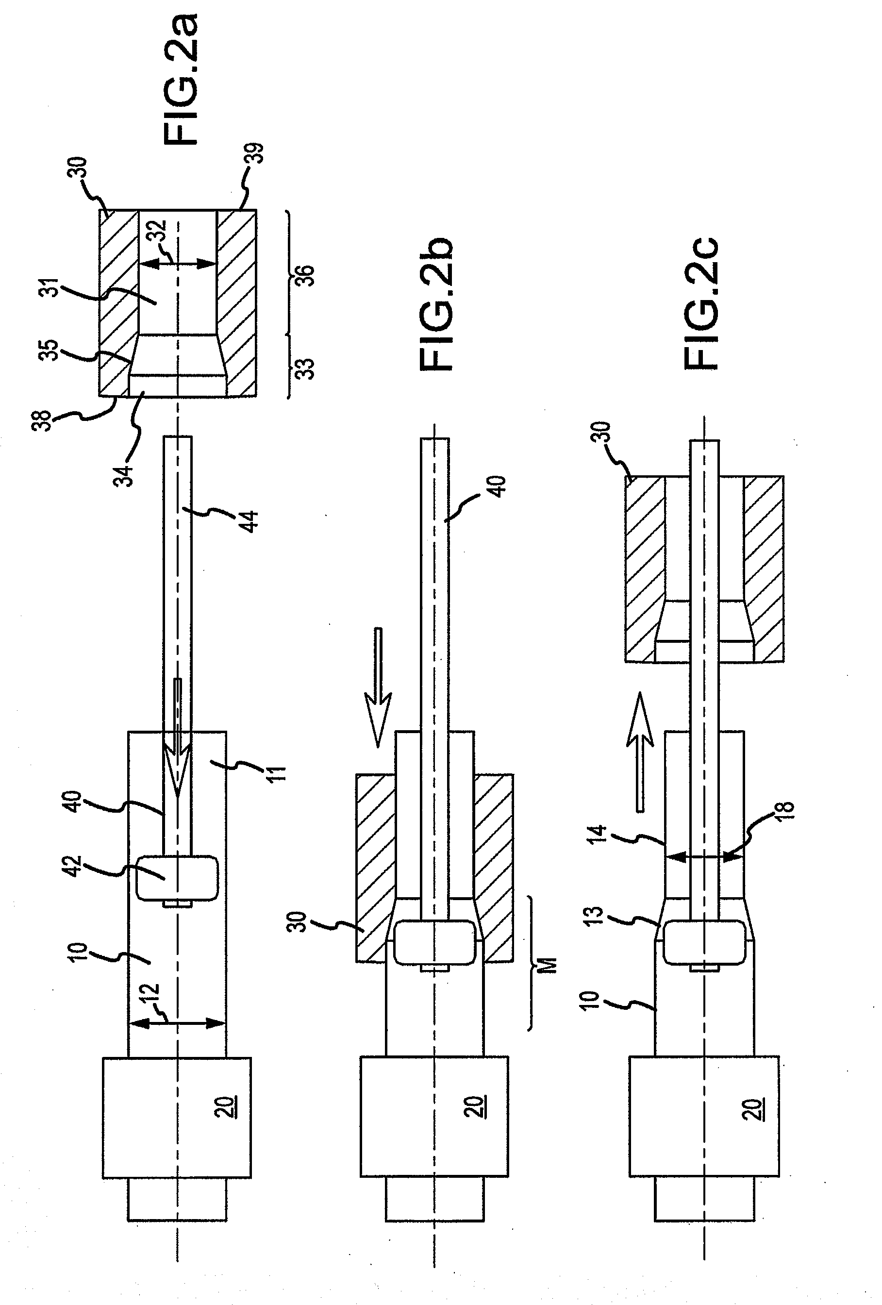
[0006] Broadly, the instant invention relates to methods and systems for reducing the stress state of compressed ends of a compressed aluminum tube with restricted or no loss of mechanical strength. The instant methods and systems may provide a reduced tensile residual stress state, or even a compressive residual stress state, after compression, which may improve weld quality while maintaining design interferences and mechanical transfer of torque.

Problems solved by technology

In some cases, the degree of diameter reduction can impart a tensile residual stress state in the swaged portion that adversely effects weld quality, design interference fit, and the fatigue performance of the drive shaft.
Thermal techniques are known for treating wrought aluminum products having forming induced stress, such as those induced via swaging processes, but such thermal techniques are generally not effective in relieving stress without substantially reducing the mechanical properties of the material.

Method used


Image

  • Methods and systems for reducing tensile residual stresses in compressed tubing and metal tubing products produced from same
  • Methods and systems for reducing tensile residual stresses in compressed tubing and metal tubing products produced from same
  • Methods and systems for reducing tensile residual stresses in compressed tubing and metal tubing products produced from same

Examples


example 1

Production of Tubing End Via Conventional Process

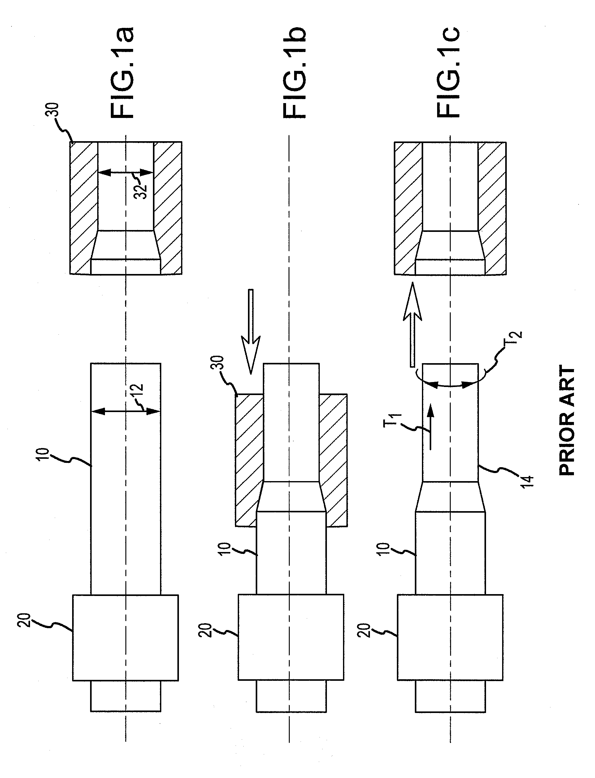
[0044] A compressed tubing end of a 6061 series aluminum alloy is produced substantially in accordance with FIGS. 1(a)-1(c) and the description associated therewith. The residual axial hoop stress of the tubing end is measured via the Espey and Sachs method. The diameter before testing is about 4.528 inches. The diameter after testing is about 4.728 inches. The residual hoop stress is measured to be about 10.17 ksi.

example 2

Production of Tubing End Via Conventional Process with Subsequent Heat Treatment

[0045] A compressed tubing end of a 6061 series aluminum alloy is produced substantially in accordance with FIGS. 1(a)-1(c) and the description associated therewith. After production, the compressed end is heat treated via conventional processes. The residual axial hoop stress of the tubing end is measured via the Espey and Sachs method. The diameter before testing is about 4.532 inches. The diameter after testing is about 4.532 inches. The residual hoop stress is measured to be about 0 ksi.

example 3

Production of Stress-Relieved Tubing End Via Expander

[0046] A compressed tubing end of a 6061 series aluminum alloy is produced substantially in accordance with FIGS. 2(a)-2(d) and the description associated therewith. After production, the residual axial hoop stress is measured via the Espey and Sachs method. The diameter before testing is about 4.525 inches. The diameter after testing is about 4.492 inches. The residual hoop stress is measured to be about −1.95 ksi.


PUM

PropertyMeasurementUnit
outer diameteraaaaaaaaaa

Abstract

Methods and systems for reducing the stress state of compressed ends of compressed tubes are disclosed. The methods and systems may provide a reduced tensile residual stress state, or even a compressive residual stress state. Tube products produced from the same are also provided.

Description

CROSS-REFERENCE TO RELATED APPLICATIONS [0001] This patent application claims priority to U.S. Provisional Patent Application No. 60 / 824,036, filed Aug. 30, 2006, and entitled, “METHODS AND SYSTEMS FOR REDUCING FORMING INDUCED TENSILE RESIDUE STRESS IN COMPRESSED TUBING”, which is incorporated herein by reference. This patent application is also related to PCT Patent Application No. PCT / U.S.07 / 77270, filed Aug. 30, 2007, which is incorporated herein by reference.BACKGROUND OF THE INVENTION [0002] Substituting large diameter, one-piece aluminum drive shafts for conventional two-piece steel constructions has become a popular means of reducing NVH (Noise, Vibration, and Harshness), cost, and weight in passenger car and light truck drive lines. In order to make use of common yokes or end fitting configurations, tubes ends are generally reduced in size via swaging to an inside diameter that appropriately matches the end fittings' mating surface. [0003] A conventional system for reducing ...

Claims


Application Information

Patent Timeline
Patent Type & Authority Applications(United States)
IPC IPC(8): B21D41/00
CPCB21C5/00B21C37/16B21K21/12B21K1/063B21K1/12B21C37/30
Inventor DICKSON, JOHN A.GADBERY, DANBENDZINSKI, DUANE
Owner ARCONIC TECH LLC
Learn More