Alternative Left/Right Bank EGR Loop Operation to Improve Fouling Resistance During Low Mass Flow Engine Mode

Inactive Publication Date: 2008-03-13
FORD GLOBAL TECH LLC
View PDF8 Cites 37 Cited by
  • Summary
  • Abstract
  • Description
  • Claims
  • Application Information

AI Technical Summary

Problems solved by technology

However, the inventors herein have recognized a disadvantage with such an approach.
Thi

Method used


Image

  • Alternative Left/Right Bank EGR Loop Operation to Improve Fouling Resistance During Low Mass Flow Engine Mode
  • Alternative Left/Right Bank EGR Loop Operation to Improve Fouling Resistance During Low Mass Flow Engine Mode
  • Alternative Left/Right Bank EGR Loop Operation to Improve Fouling Resistance During Low Mass Flow Engine Mode

Examples


Embodiment Construction

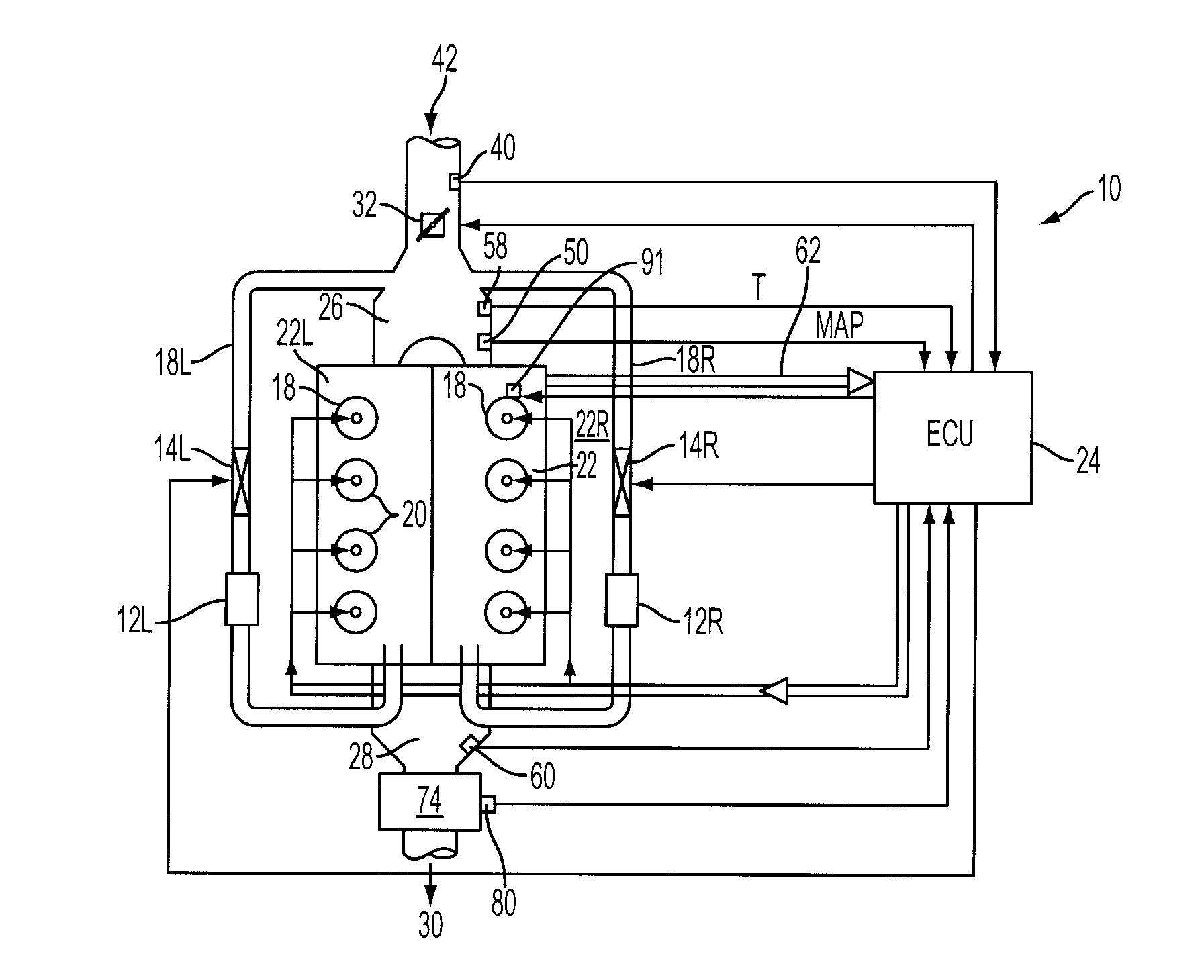
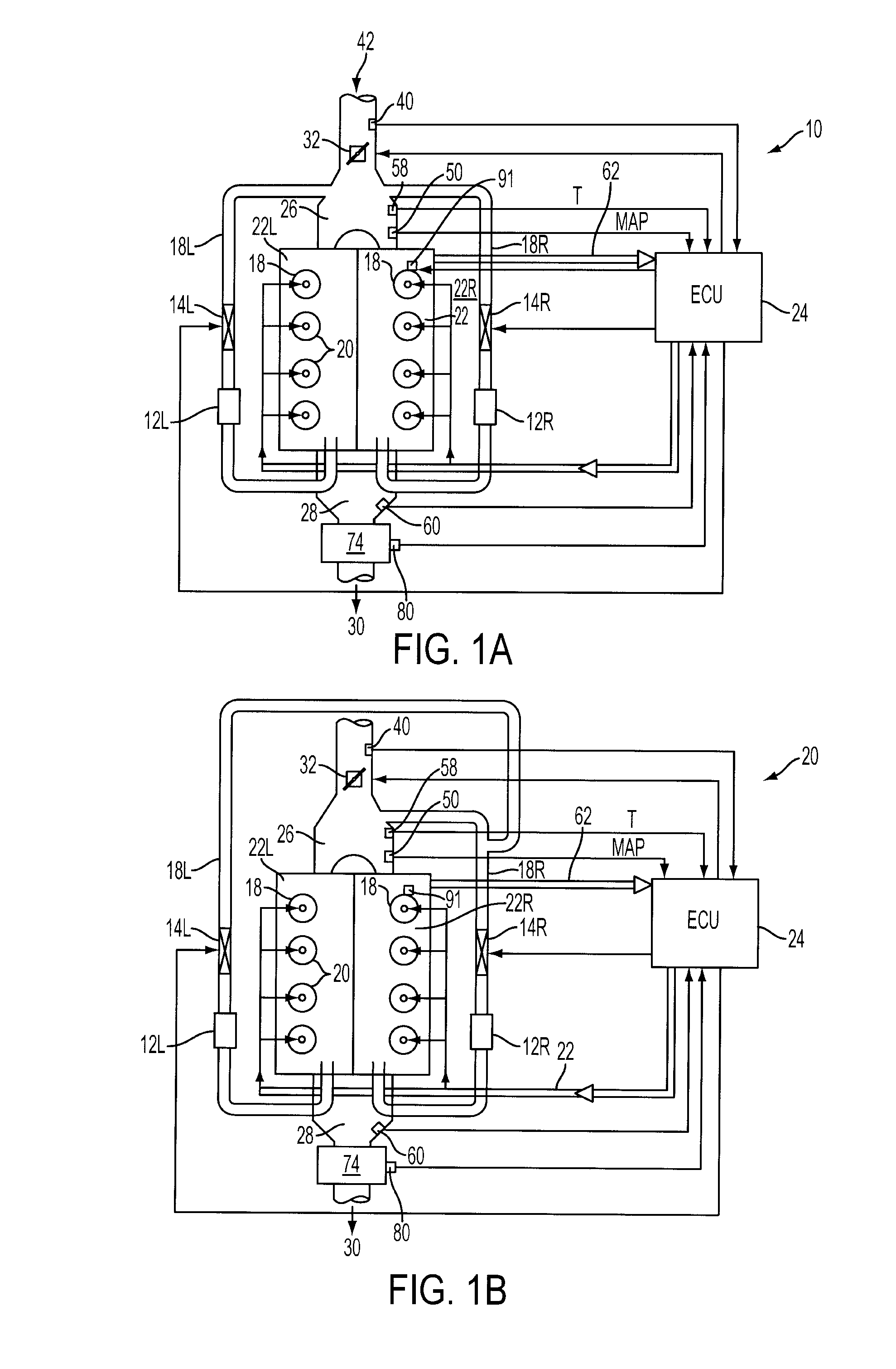
[0020]FIG. 1A is a schematic diagram of a diesel engine system 10. A representative engine block 16 is shown having eight cylinders 18 with four cylinders disposed in the left bank 22L and four cylinders disposed in the right bank 22R, although more or fewer cylinders may be used if desired. While FIG. 1A shows a configuration with two banks in a left / right configuration, the engine may be configured in a variety of ways, and cylinders may be grouped in a variety of ways. For example, an inline engine may be used, such as an I-6, where three cylinders are in a first group and a different three cylinders are in a second group, where each group may have a separate or common intake and / or exhaust manifolds or sections.

[0021]Each of the cylinder or combustion chambers 18 may include a direct-injection fuel injector 20. For example, a common rail system may be used to deliver fuel to the cylinders. The duty cycle of the fuel injectors 20 may be determined by the engine control unit (ECU)...


PUM


Abstract

A system for a vehicle, comprising of a diesel engine having an intake system and an exhaust system, a first EGR loop coupled between said intake system and said exhaust system and having a first valve and a first cooler located therein, a second EGR loop coupled between said intake system and said exhaust system and having a second valve and a second cooler located therein, and a control system operating the first and second valves in a first condition where both valves provide EGR flow to the engine, and at least temporarily increasing flow in the first EGR loop and decreasing flow in the second EGR loop when EGR flow is decreased to a condition where buildup in one of said coolers is increased.

Description

FIELD [0001]The present application relates to system and method to reduce the build up of particulates in EGR coolers of a diesel engine.BACKGROUND AND SUMMARY [0002]Exhaust gas recirculation (EGR) systems may be used in diesel internal combustion engines to reduce NOx emissions. In the combustion chambers, the recirculated exhaust gas acts as an inert gas, thus lowering the flame and in-cylinder gas temperature and decreasing the formation of NOx. Further, EGR systems may include coolers to cool the exhaust gas before it is introduced into an intake manifold of a diesel engine.[0003]One approach to utilize multiple EGR loops is described in U.S. 2005 / 0028515. In this system, an exhaust control apparatus is applied to an internal combustion engine in which intake sides of a plurality of cylinder groups are connected to a common intake passage and exhaust sides thereof are connected to different exhaust passages. The system includes an exhaust gas flow amount adjusting device for ca...

Claims


Application Information

Patent Timeline
IPC IPC(8): F02M25/07
CPCF02B3/06F02D41/0065F02D41/0082F02M25/0707Y02T10/47F02M25/0732F02M25/0744F02M25/0748F02M25/0709F02M26/05F02M26/06F02M26/24F02M26/38F02M26/42Y02T10/40F02D41/0047
Inventor GRANDAS, JOSEPH
Owner FORD GLOBAL TECH LLC
Why Eureka
Try Eureka