Thermal compensation in semiconductor lasers

a semiconductor laser and thermal compensation technology, applied in lasers, laser cooling arrangements, laser details, etc., can solve the problems of difficult package fabrication, large on/off ratio, high modulation speed, etc., and achieve high modulation speed, optimum output power, and no noise. excessive

Inactive Publication Date: 2008-03-13
CORNING INC
View PDF11 Cites 37 Cited by
  • Summary
  • Abstract
  • Description
  • Claims
  • Application Information

AI Technical Summary

Benefits of technology

[0004]Given the challenges associated with wavelength matching and stabilization in developing laser sources using second harmonic generation, the present inventors have recognized potential benefits for semiconductor lasers that can be actively tuned in order to achieve optimum output power through proper wavelength matching with SHG crystals and other wavelength conversion devices. For example, the present inventors have recognized that short wavelength devices can be modulated at high speeds without excessive noise while maintaining a non-fluctuating second harmonic output power if the wavelength of the semiconductor is maintained at a stable value during operation. For video applications, the optical power (green light, for example) often needs to be modulated at a fundamental frequency of 10 to 100 MHz and at extinction ratio of ˜40 dB. This combination of high modulation speed and large on / off ratio remain a challenging task to overcome. The present invention relates to methods for modulating a semiconductor laser and wavelength matching to a wavelength converter using monolithic micro-heaters integrated in the semiconductor laser. The present invention also relates to wavelength matching and stabilization in laser sources in general, without regard to whether the laser is modulated or whether second harmonic generation is utilized in the laser source.

Problems solved by technology

Accordingly, it is difficult to fabricate a package where the laser diode and the SHG crystal are perfectly wavelength matched.
This combination of high modulation speed and large on / off ratio remain a challenging task to overcome.

Method used


Image

  • Thermal compensation in semiconductor lasers
  • Thermal compensation in semiconductor lasers
  • Thermal compensation in semiconductor lasers

Examples


Embodiment Construction

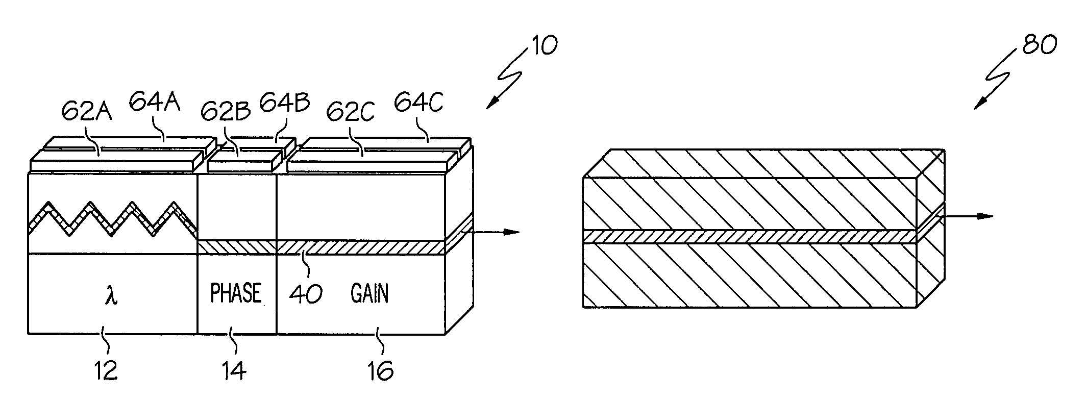
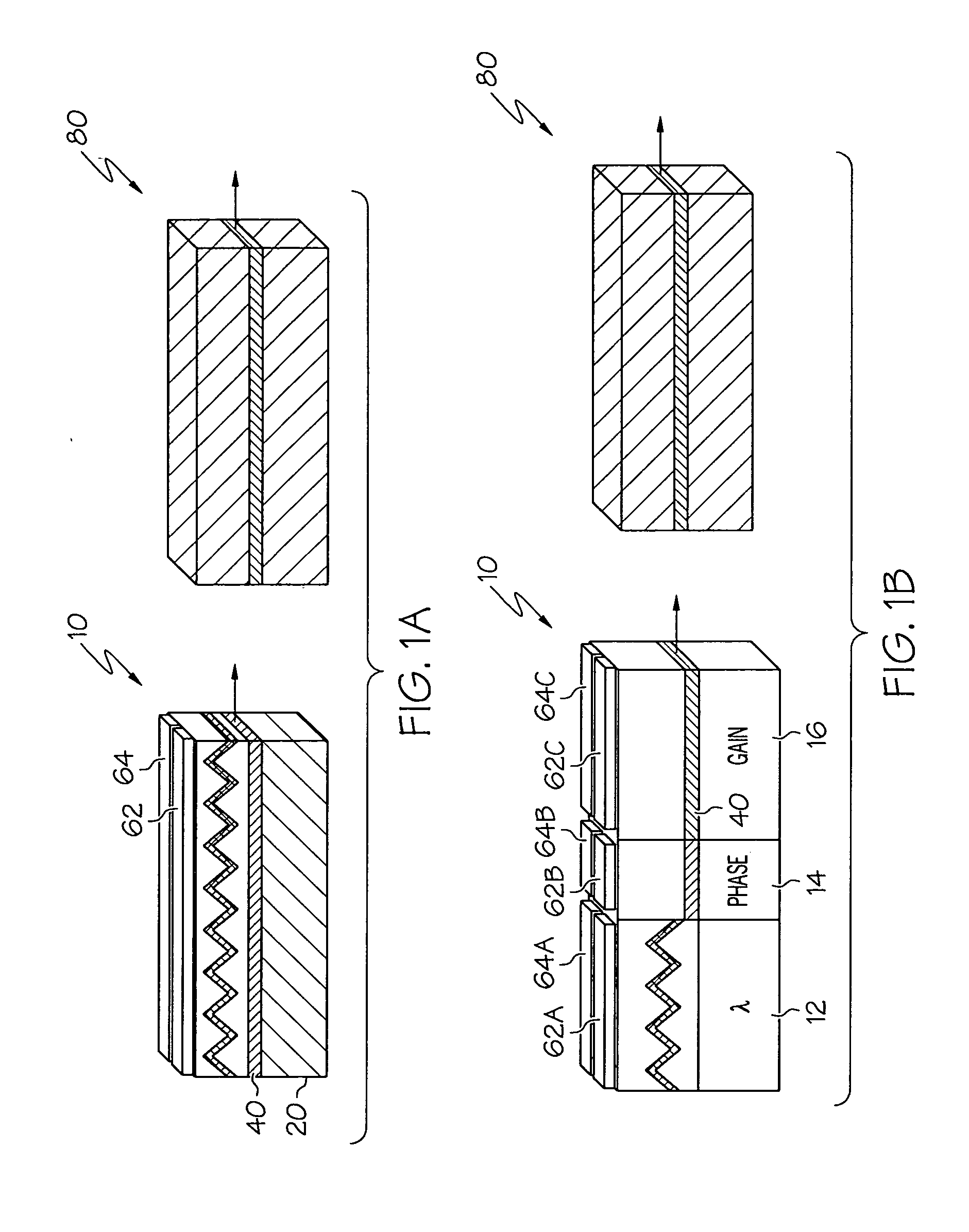
[0019]FIGS. 1A and 1B, are respective schematic illustrations of DFB and DBR semiconductor lasers 10 optically coupled to light wavelength conversion devices 80. The light beam emitted by the semiconductor laser 10 can be either directly coupled into the waveguide of the wavelength conversion device 80 or can be coupled through collimating and focusing optics or some type of suitable optical element or optical system. The wavelength conversion device 80 converts the incident light into higher harmonic waves and outputs the converted signal.

[0020]As will be appreciated by those familiar with DFB laser design, the DFB semiconductor laser 10 illustrated schematically in FIG. 1A comprises a distributed feedback grating that extends generally along the direction of a ridge waveguide 40 incorporated within the laser 10. Driving electrodes, not shown in FIG. 1A but discussed below with reference to FIGS. 4-6, are incorporated in the laser device to generate the electrical bias VBIAS necess...


PUM


Abstract

The present invention relates to methods for modulating a semiconductor laser and wavelength matching to a wavelength converter using monolithic micro-heaters integrated in the semiconductor laser. The present invention also relates to wavelength matching and stabilization in laser sources in general, without regard to whether the laser is modulated or whether second harmonic generation is utilized in the laser source. According to one embodiment of the present invention, a method of compensating for thermally induced patterning effects in a semiconductor laser is provided where the laser's heating element driving current IH is set to a relatively high magnitude when the laser's driving current ID is at a relatively low magnitude. Additional embodiments are disclosed and claimed.

Description

BACKGROUND OF THE INVENTION[0001]The present invention relates generally to semiconductor lasers and, more particularly to the use of micro-heaters to compensate for mode hops and wavelength drift in semiconductor lasers.SUMMARY OF THE INVENTION[0002]The present invention relates generally to semiconductor lasers, which may be configured in a variety of ways. For example and by way of illustration, not limitation, short wavelength sources can be configured for high-speed modulation by combining a single-wavelength semiconductor laser, such as a distributed feedback (DFB) laser or a distributed Bragg reflector (DBR) laser, with a light wavelength conversion device, such as a second harmonic generation (SHG) crystal. The SHG crystal can be configured to generate higher harmonic waves of the fundamental laser signal by tuning, for example, a 1060 nm DBR or DFB laser to the spectral center of a SHG crystal, which converts the wavelength to 530 nm. However, the wavelength conversion effi...

Claims


Application Information

Patent Timeline
Patent Type & Authority Applications(United States)
IPC IPC(8): H01S3/04
CPCH01S5/024H01S5/0261H01S5/0425H01S5/0612H01S5/2231H01S5/06251H01S5/06256H01S5/22H01S5/06213H01S5/02453H01S5/04256H01S5/026H01S5/042
Inventor BHATIA, VIKRAMHU, MARTIN HAILIU, XINGSHENGLOEBER, DAVID AUGUST SNIEZEKRICKETTS, DANIEL OHENZAH, CHUNG-EN
Owner CORNING INC
Why Eureka
Try Eureka