Amplifier and Method of Amplification

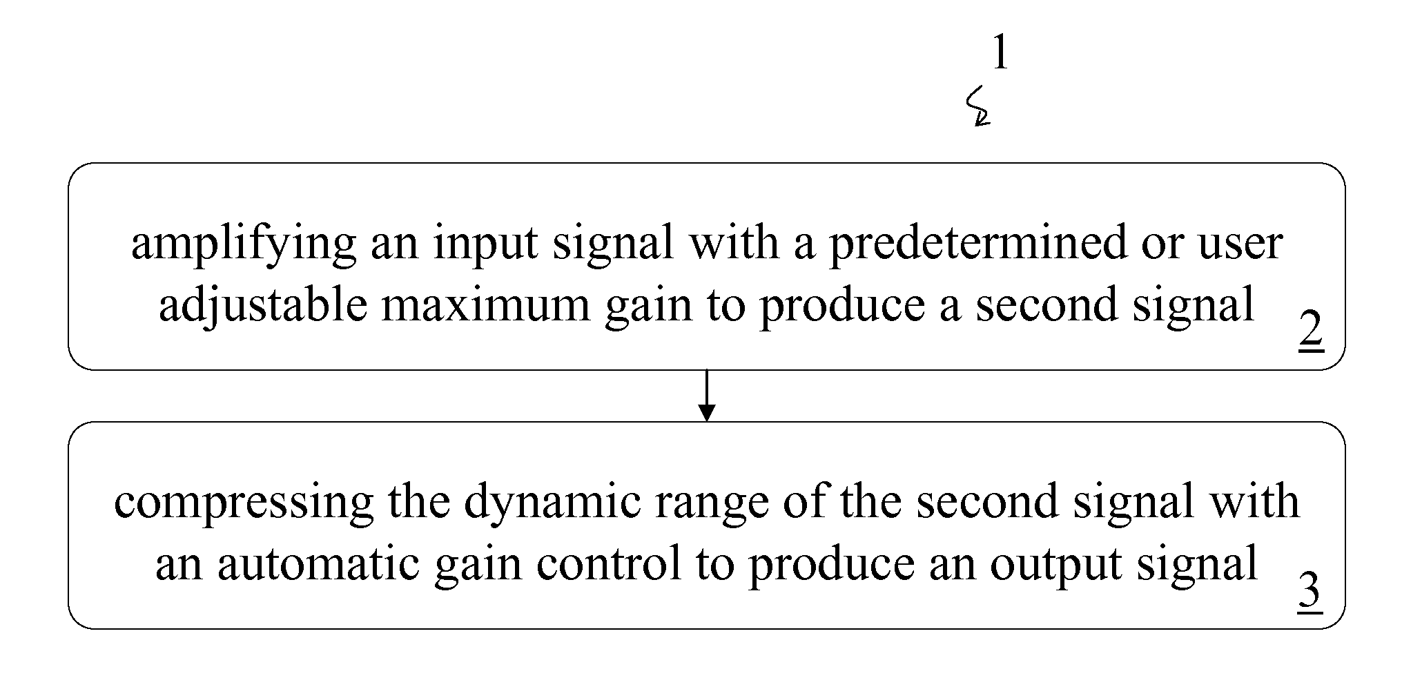
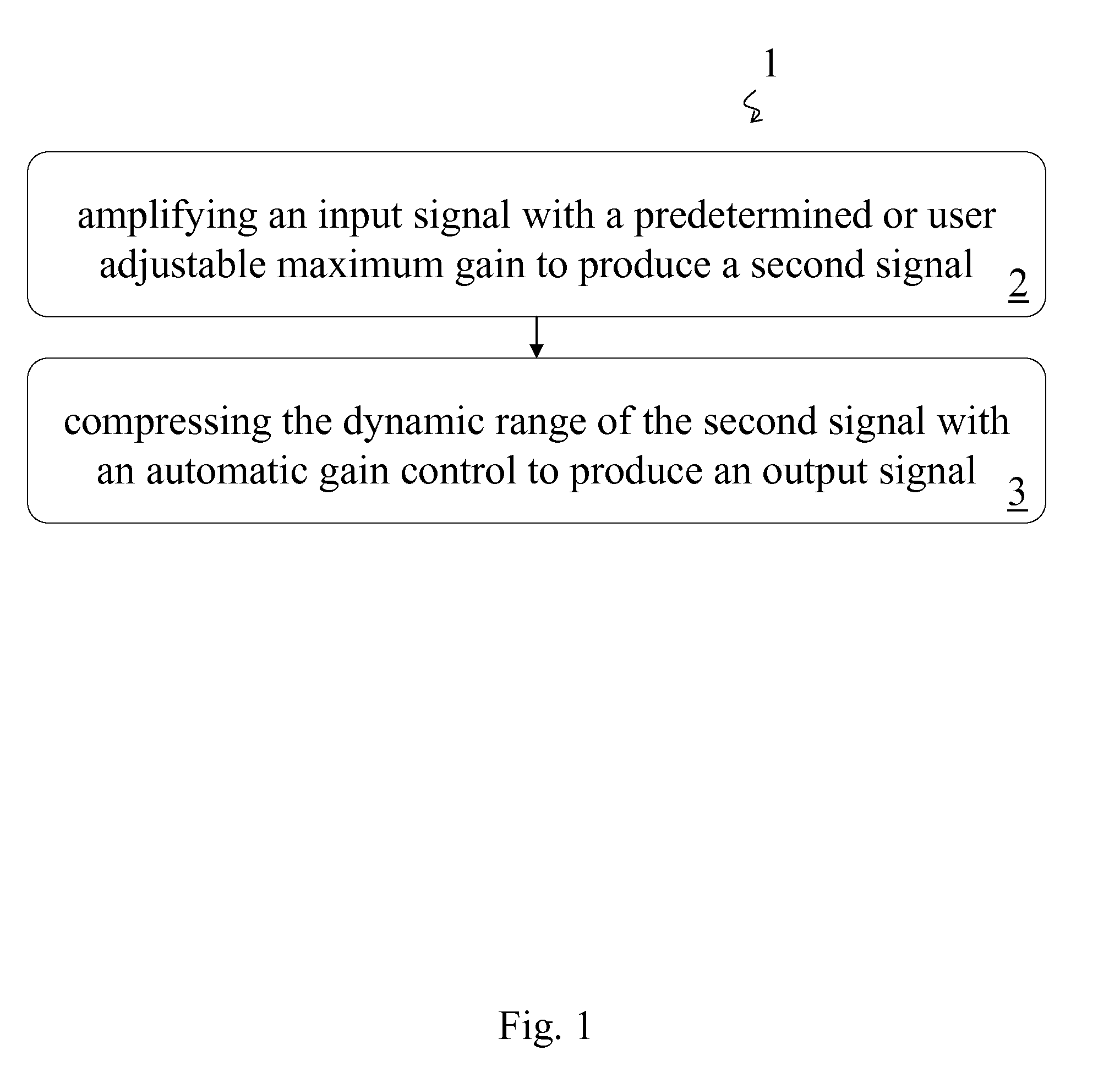
a technology of amplifier and amplifier, applied in the direction of volume compression/expansion, frequency response correction, untuned/low-frequency amplifier, etc., can solve the problem of insufficient unity gain of loud sounds, impaired cochlear function,

Inactive Publication Date: 2008-03-20
REVITRONIX
View PDF6 Cites 97 Cited by
  • Summary
  • Abstract
  • Description
  • Claims
  • Application Information

AI Technical Summary

Benefits of technology

[0021]The apparatus may further comprise a signal source, a band filter, a signal combining device, an equalization filter, an output-limiting compression amplifier and / or an output device. The signal source may be a microphone, a telephone line, a storage device, or a wireless receiver. The storage device may be a record, a compact disk, an audio tape, a video tape, a digital video disk, a computer hard drive, a flash memory, or a read-only memory. The band filter may be a low pass, high pass, or band pass filter. The equalization filter may fine-tune frequency response, compensate for deficiencies in frequency response of an output device, or achieve a diffuse field reference. The output device may be an earphone, a telephone receiver, a hearing aid receiver, or a speaker. The output device may correct the frequency response of the output signal to achieve a diffuse-field equivalent response. The output-limiting compressor may assure that the output does not exceed safe listening levels, comfortable listening levels, and / or maximum operating levels.

Problems solved by technology

When the hearing loss is substantial (i.e., greater than 60 dB), unity gain for loud sounds is insufficient for optimal intelligibility of those loud sounds.
In addition to physiological hearing loss being the cause of impaired cochlear function, impaired cochlear function can be caused by adverse external listening conditions.

Method used


Image

  • Amplifier and Method of Amplification
  • Amplifier and Method of Amplification
  • Amplifier and Method of Amplification

Examples


example implementation

[0059]

[0060]For example, there may be two band filters, creating high-pass and low-pass band channels. The characteristic of the low-pass filter may be such that the band gain begins to fall above 500 Hz and is 6 dB down at 1000 Hz. The characteristic of the high-pass filter may be such that the band gain begins to fall below 2000 Hz and is 6 dB down at 1000 Hz. Preferably, when the two bands have equal gain, the broadband frequency response of the recombined signal is flat.

[0061]A user operated gain (“Volume”) control may set the maximum gain of the high-frequency band amplifier 39. A “Tone” control may set the low-frequency band gain, or may set the ratio of high- to low-frequency band gains. The tone control may have the constraint that the total low-frequency band gain cannot exceed the total high-frequency band gain, and may also have the further constraint that the total low-frequency band gain cannot be more that 30 dB less than the total high-frequency band gain. Setting the...

example curves

[0071]

[0072]FIG. 8 through FIG. 13 are example sets of curves describing the functioning of the amplifier. The particular values in this description are as implemented in a telephone system by a telephone manufacturer; however, the actual numbers of Volume and Tone settings may be changed, leading to different numbers of possible I / O and frequency response curves. In FIG. 8 and FIG. 9 are shown input / output (I / O) curves, which are samples of the numerous possible low-frequency and high-frequency (LF and HF) I / O pairs in this implementation. Only a sample of curves at the Normal (FIG. 8) and Treble (FIG. 9) extremes is shown. The curves not shown may be interpolated across numerous possible Volume (gain) settings, such as between 0 and 50 dB, and numerous possible Tone settings per Volume setting, between Normal and Treble. The number of Tone settings may be chosen to increase as the Volume setting increases.

[0073]In FIG. 10 and FIG. 11 are shown output versus frequency response curv...


PUM


Abstract

A method of amplification includes amplifying an input signal with a predetermined or user adjustable maximum gain to produce a second signal and compressing the dynamic range of the second signal with an automatic gain control to produce an output signal. The compression ratio of the automatic gain control is greater than one for output signals below a predetermined threshold output signal level and is essentially one for output signals above the predetermined threshold output signal level. The compression ratio may be predetermined or the method may include determining the compression ratio of the automatic gain control. The compression ratio may be determined according to the amplitude of the output signal or according to an input-output curve. The input-output curve my be predetermined and may be selected according to the auditory needs of a listener. Preferably the input-output curve is determined according to the predetermined or user adjustable maximum gain.

Description

CROSS REFERENCE TO RELATED APPLICATIONS[0001]The present application is a continuation-in-part of provisional U.S. patent application No. 60826069 filed on Sep. 18, 2006, which is herein incorporated by reference.BACKGROUND[0002]The term “compression” refers to automatic gain control (AGC) that reduces the overall dynamic range of a signal. In other words, compression reduces the range between the softest and the loudest signals. Ideally, compression does nothing to the waveform of a signal; it acts only on the overall level (volume) of the signal. In general, there are two types of compression: upward compression, and downward compression. Upward (or low-level) compression raises the level of low-level inputs (automatically turns up the volume for soft sounds). Downward (or high-level) compression lowers the level of high-level signals (automatically turns down the volume for loud sounds). A compression device may be configured to provide either or both of these types of compressio...

Claims


Application Information

Patent Timeline
Patent Type & Authority Applications(United States)
IPC IPC(8): H04R25/00H03G7/00
CPCH03G5/025H03G7/002H04R3/04H03G9/025H04R2420/07H04R2499/11H04R25/356
Inventor REVIT, LAWRENCE JAY
Owner REVITRONIX
Why Eureka
Try Eureka