
Electrochemical Treatment Of Substrates

a technology of electrochemical treatment and substrate, which is applied in the direction of isotope separation, chemical/physical/physicochemical processes, energy-based chemical/physical/chemical processes, etc., can solve the problems of increasing the difficulty and cost of connecting each electrode independently, and reducing the efficiency of product production, so as to increase the throughput and efficiency of product production

Inactive Publication Date: 2008-03-20
EGELAND RYAN D
View PDF2 Cites 12 Cited by
  • Summary
  • Abstract
  • Description
  • Claims
  • Application Information

AI Technical Summary

Benefits of technology

"The present invention provides a method and device for electrochemically treating a substrate with high resolution. The method involves using a common first electrode that is in contact with an electrolyte and a plurality of individually addressable second electrodes. The second electrodes contain individually addressable second redox products that can modify the substrate. The method simplifies the electrical connections and the electronics required to pattern the substrate at very high resolution. The device includes a common first electrode and a plurality of individually addressable second electrodes. The common first electrode is a cathode and may have a patterned geometry to define cells. The cells may be uniform in size or of a range of sizes. The method and device can be used for electrochemical patterning at high resolution."

Problems solved by technology

However, a bulk solution containing a buffering or scavenging substance has the disadvantage of quenching not only those reagents that diffuse away from specific electrodes, but also reagents which are intended to react at a substrate adjacent to a specific electrode.
However, as the number of electrodes on a device increases, it becomes more difficult and costly to connect each electrode independently.

Method used


Image

  • Electrochemical Treatment Of Substrates
  • Electrochemical Treatment Of Substrates
  • Electrochemical Treatment Of Substrates

Examples


first embodiment

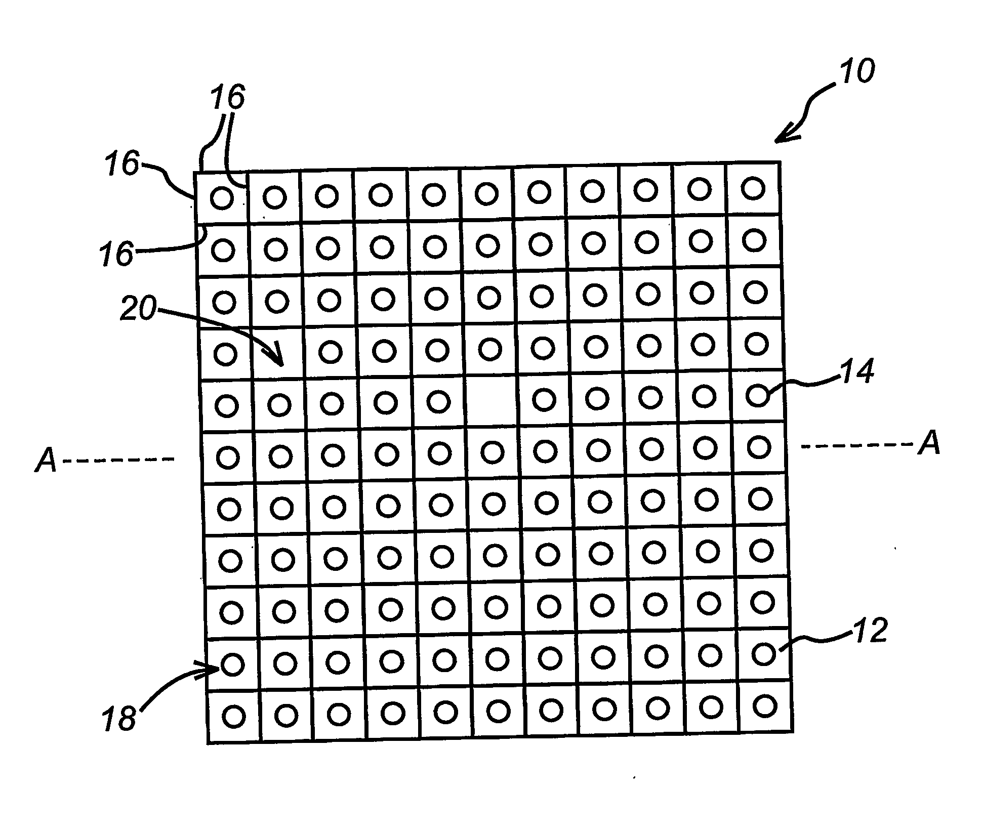
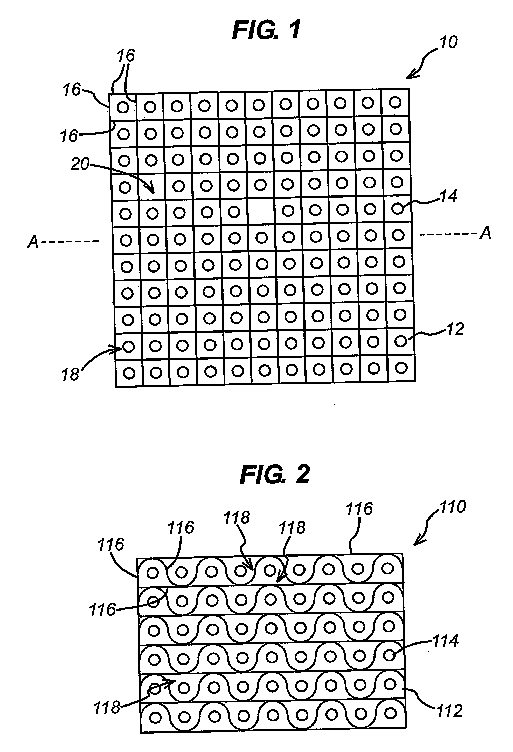
[0147]FIGS. 1 to 6 show various embodiments of a device (10) for electrochemically modifying the surface of a substrate (not shown). In FIG. 1, the device (10) has an array of individually addressable second electrodes (14). The second electrodes (14) are circular and are mounted on a support (12). A common first electrode (16) is arranged on the support (12) in the form of a grid. The common first electrode (16) defines cells (18, 20). Most cells (18) contain a single second electrode. A minority of cells (20) do not contain a second electrode.

second embodiment

[0148]In FIG. 2, there is shown a portion of a device (110). The device (116) has an array of individually addressable second electrodes (114). The second electrodes (114) are mounted on a support (112). A common first electrode (116) is arranged on the support (112) in tessellating pattern. The common first electrode (116) defines cells (118). In the portion of the device (110) shown in FIG. 2, a single second electrode (114) is positioned within each cell (118).

third embodiment

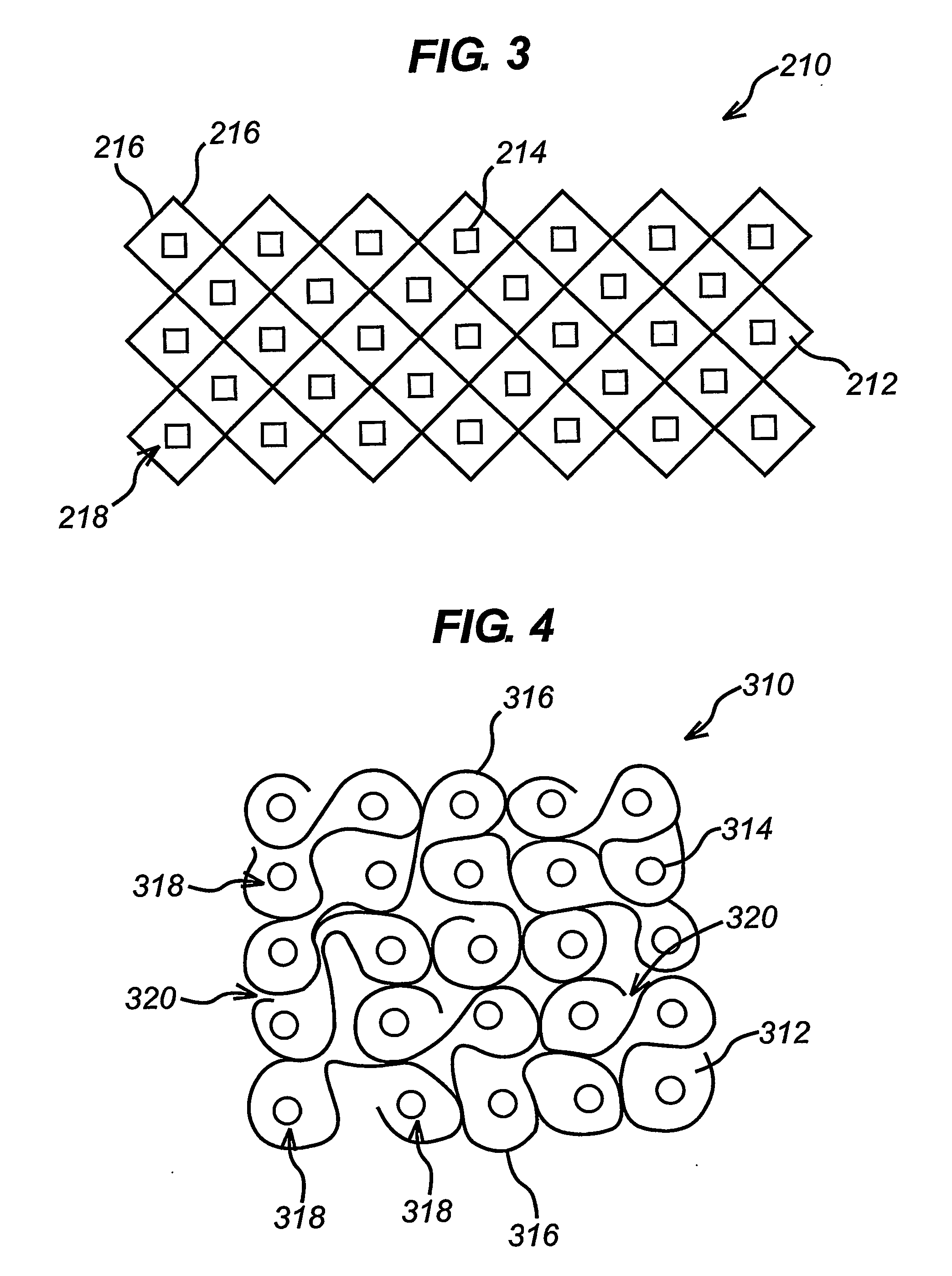
[0149]In the device (210), a portion of which is shown in FIG. 3, there is an array of individually addressable second electrodes (214). The second electrodes (214) have a square shape and are mounted on a support (212). A common first electrode (216) is arranged on the support in a net-like pattern. The common first electrode (216) defines cells (218). In the portion of the device (210) shown in FIG. 3, a single second electrode (214) is positioned within each cell (218).


PUM

PropertyMeasurementUnit
distanceaaaaaaaaaa
temperatureaaaaaaaaaa

Abstract

A method of electrochemically treating a substrate is provided comprising the steps of: (a) providing an electrolyte in contact with the substrate; (b) providing a device which faces the substrate and is in contact with the electrolyte, the device having: (i) a common first electrode arranged to define cells therein; and (ii) a plurality of individually addressable second electrodes, wherein a plurality of the cells contain individually addressable second electrodes; and (c) altering the potential of at least one of the second electrodes relative to the common first electrode so that: (i) the common first electrode generates a first redox product; and (ii) the at least one of the second electrodes generate a second redox product which is able to modify a region of the substrate facing the at least one electrodes, wherein the electrolyte is such that the second redox product is quenchable by the first redox product.

Description

[0001]All documents cited herein are incorporated by reference in their entirety.TECHNICAL FIELD[0002]This invention is in the field of electrochemical patterning of substrates. More particularly, this invention relates to a method of electrochemically modifying substrates and to a device that may be used in such methods.BACKGROUND ART[0003]There are many occasions where it is required to provide a pattern of a material on a substrate. Examples of such patterned substrates include semiconductor chips and devices on printed circuit boards. More recently, patterns of oligonucleotides bound to a solid surface have been produced to form DNA chips. DNA chips comprise arrays of various DNA sequences bound to a substrate at specific sites.[0004]Various methods of fabricating patterned substrates exist. Photolithography is an example of such a method. In photolithography, specific regions of a substrate surface are covered with a photolithographic mask and the exposed regions are modified b...

Claims


Application Information

Patent Timeline
Patent Type & Authority Applications(United States)
IPC IPC(8): C40B50/00B01J19/08C40B60/14C25F3/02B01J19/00C40B40/06C40B40/10H01L51/50H01L51/56
CPCB01J19/0046B01J2219/00317B01J2219/00585B01J2219/00653B01J2219/00659H01L51/56B01J2219/00722B01J2219/00725C40B40/06C40B40/10C40B60/14B01J2219/00713H10K71/40H10K71/60H10K71/00
Inventor EGELAND, RYAN D.
Owner EGELAND RYAN D
Learn More