Motivating fluid vacuum pump

a vacuum pump and driving agent technology, applied in the direction of pumping, positive displacement liquid engine, flexible member pump, etc., can solve the problems of small measures and the required rotational speed for the creation of displacement, the inability to sensibly integrate the pump into the system with the microcomponents, and the inability to achieve the displacement. the effect of a small displacemen

Inactive Publication Date: 2008-03-27
BAYER TECH SERVICES GMBH
View PDF8 Cites 5 Cited by
  • Summary
  • Abstract
  • Description
  • Claims
  • Application Information

AI Technical Summary

Benefits of technology

[0012] The novelty of the invention lies in the conversion of this principle into a miniaturized form, preferably into a planar form adequate for microsystem techniques. Resulting from this utilization of miniaturization are further advantages. Here, in the case of the driving agent vacuum pump, consisting of an evaporating chamber at high pressure and a pump chamber at low pressure, separated by a jet arrangement, it is provided that the pumping effect is achieved by a flow at high speed through a preferably planar arrangement of jets vertical in depth and located between two parallel plates which close the chambers in the jet region. Further an opening is provided in the pump chamber above the jet arrangement to draw in the medium to be pumped and an opening for the discharge of the compressed gas is provided below the jet arrangement. A planar jet arrangement made of, for example, one or two Laval jets is used, for a purpose of expanding and accelerating selectively up to supersonic speed a liquid, gas or vapor phase driving agent under pressure. With this the jet stream can achieve supersonic speed.
[0016] To achieve a high as possible pressure difference with only one microdriving agent pump several jet stages can be operated behind one another so that the evacuated gas in each stage is further compressed. A variation of the used driving agent and of the used evaporation temperature likewise makes possible an operation in different pressure regions.
[0017] To avoid a contamination of the jets or of the jet delivery channels by small particles, a particle filter can, for example, be integrated in the evaporation chamber. A similar filter can also be integrated into the delivery and discharge channels at the input and output of the evaporating chamber.
[0020] Moreover, in a further development a connection is provided between the evaporating chamber and a pump chamber through which a condensed driving agent is returned and which connection at the same time serves as a pressure stage. A return of the condensed driving agent from the pump chamber to the evaporating chamber can, for example, be carried out by one or more capillary shaped channels which is or are covered by a layer having an outer surface energy higher than that of the pump chamber. These measures make it possible to operate the micropump independently of its position.

Problems solved by technology

Therefore these pumps cannot be sensibly integrated into systems with microcomponents (for example, sensors).
Many of the systems are limited in their application to liquid medium; only a few suit themselves to the pumping of gases or to the creation of a vacuum.
A scaling of the customary pump principles with rotating parts for the displacement of gases is, because of the very small measures and the required rotational speeds for the creation of the displacement, nearly impossible.
Disadvantageous of this however is the relatively complicated construction and the high surface area requirement of such systems, indeed because of the low achievable compression ratio, many such pumps need to be driven in a series in order to create the desired suction performance and pressure difference (see: R. M. Young, Analysis of a micromachine based vacuum pump on a chip actuated by thermal transpiration effect, J. Vac. Sci. Technol B17(2), March / April 1999; J. P. Hobson, D. B. Salzman, Review of pumping by thermal molecular pressure, J. Vac. Sci. Technol.

Method used


Image

  • Motivating fluid vacuum pump
  • Motivating fluid vacuum pump
  • Motivating fluid vacuum pump

Examples


Embodiment Construction

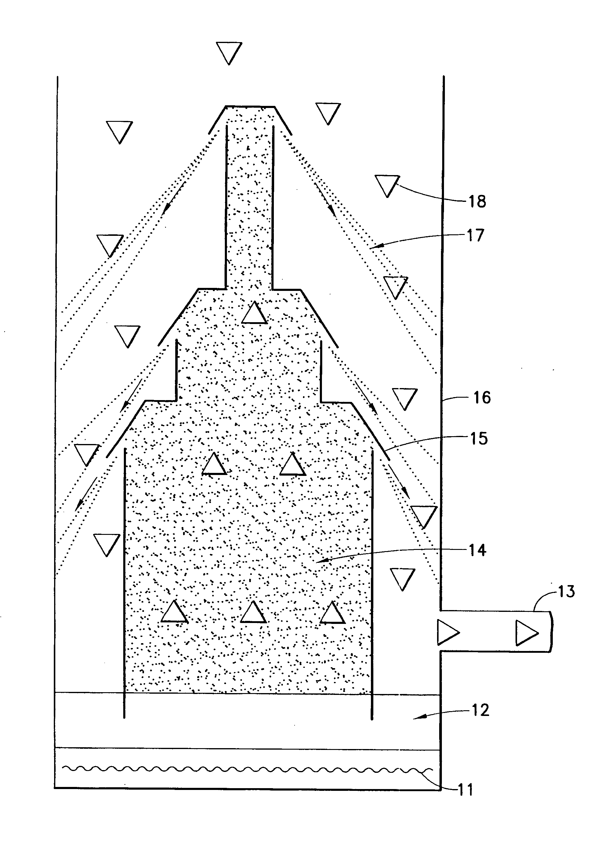
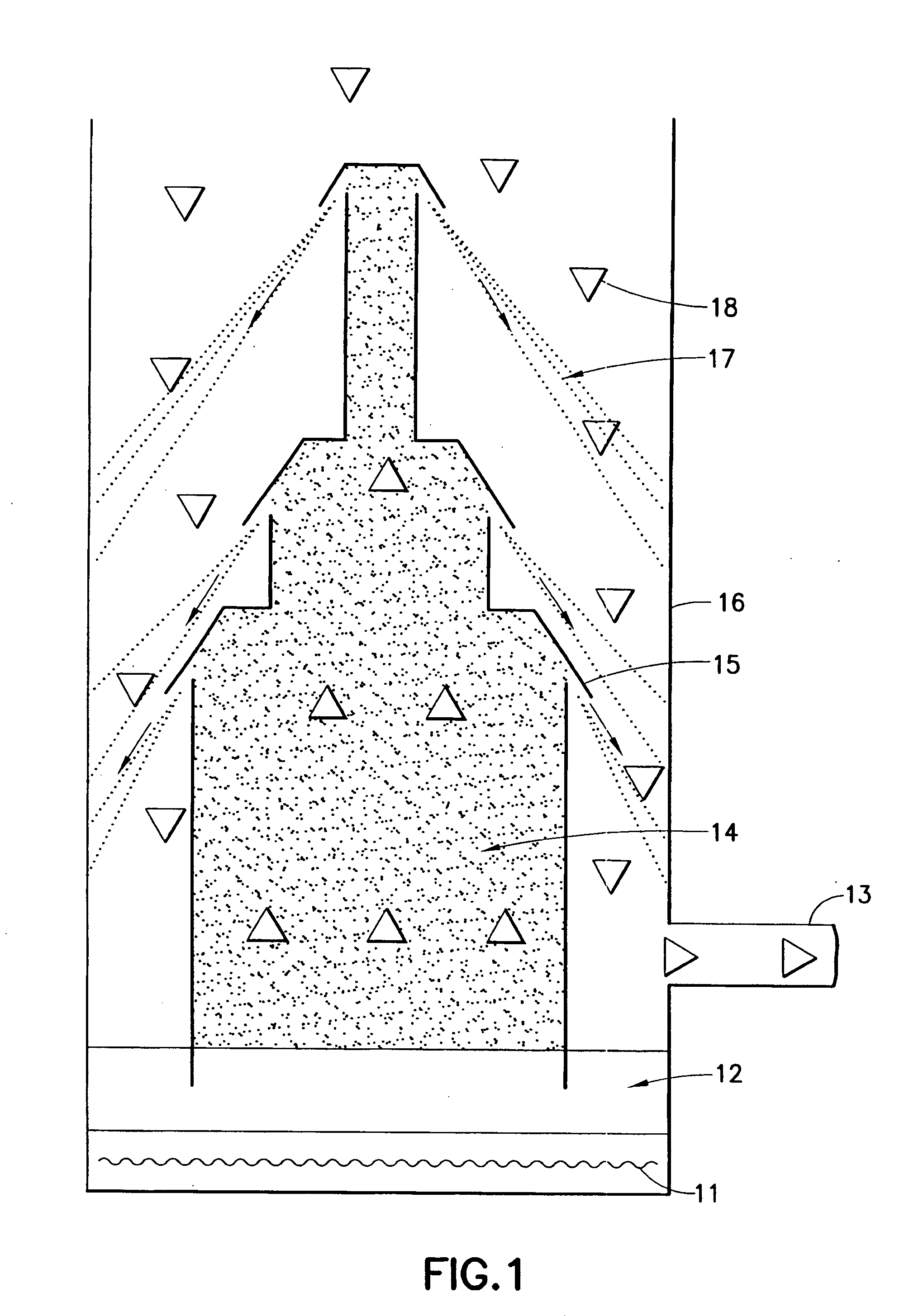
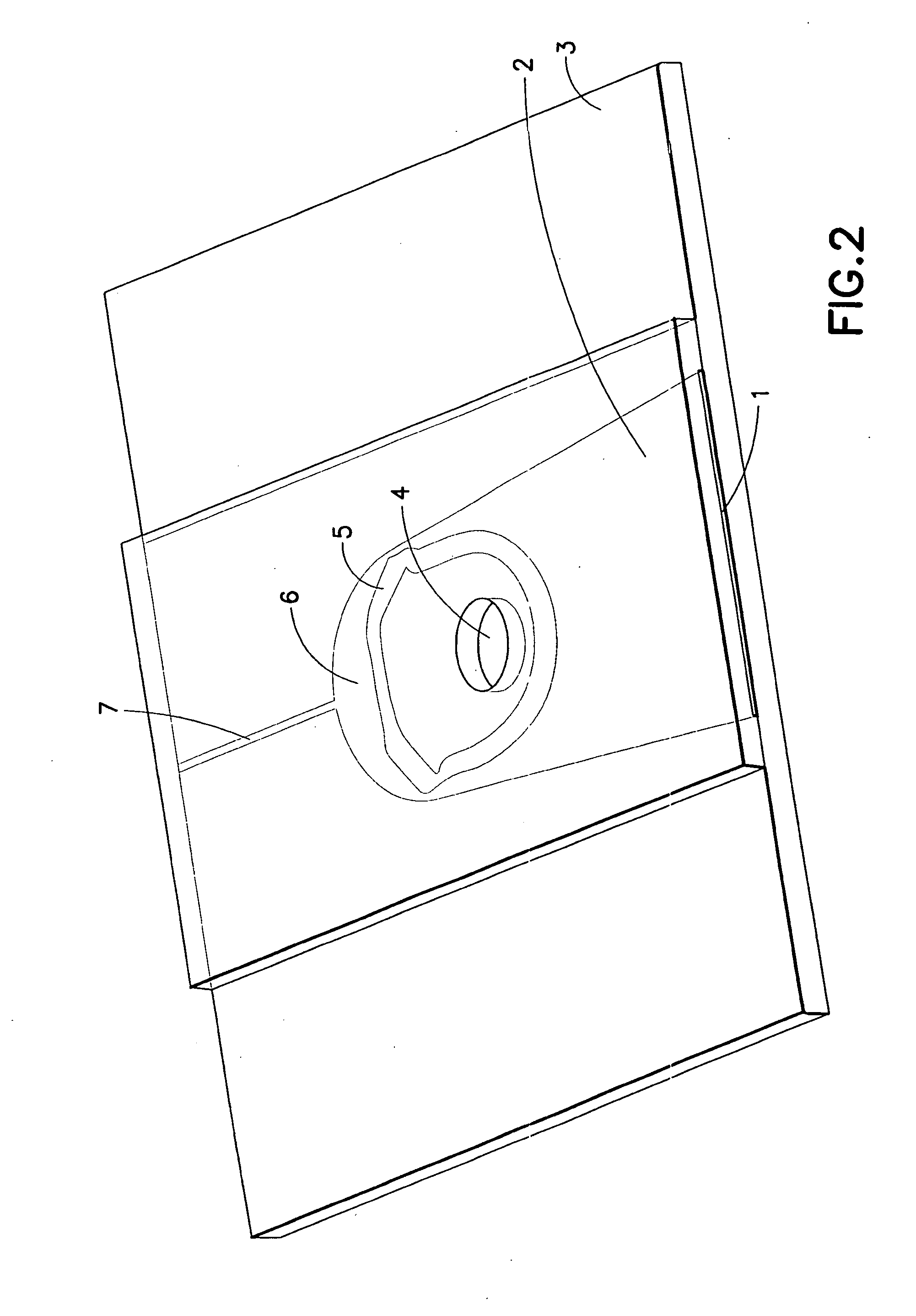
[0026] The construction of the invention consists, for example, of three substrates of which the middle substrate contains the jet structures and it is distinguished by a high heat conductibility in order to facilitate the evaporation and condensation of a liquid driving agent.

[0027] In one implementation the system or the driving agent vacuum pump is made of three substrates, the middle substrate of which because of its good heat conductibility, mechanical and chemical stability as well as its structurabilty is preferably structured by way of anisotropic etching methods, is silicon and the substrates which close its two sides are preferably because of its low thermal conductivity made of anodically bonded glass.

[0028] Moreover, in this further implementation it is advantageous if the middle substrate because of its good heat conduction is made of a galvanic metal structure, for example one made by UV-Liga technique, preferably galvanically washed on to a lower glass substrate and...


PUM


Abstract

The invention relates to a driving agent vacuum pump used in microsystems technology, comprising an evaporator chamber and a pump chamber that are separated by a jet arrangement. The design of the driving agent vacuum pump is improved by: a planar arrangement of at least one jet, which extends vertically in depth and which is situated between two, in particular, parallel plates, these plates closing the evaporator chamber and the pump chamber; an opening in the pump chamber, preferably above the jet arrangement, for drawing in a medium to be pumped, and; an opening for expelling a preferably compressed gas underneath the jet arrangement.

Description

CROSS-REFERENCE TO RELATED APPLICATIONS [0001] This application is a continuation of and claims priority to International Patent Application No. PCT / EP2005 / 011660 filed on Oct. 31, 2005, which claims priority to German Patent Application No. 10 2004 053 006.8 filed on Oct. 29, 2004, subject matter of these patent documents is incorporated by reference herein in its entirety.FIELD OF THE INVENTION [0002] The invention concerns a miniaturized driving agent vacuum pump which uses preferably planar jet and pump wall geometries structured in keeping with microsystem technology and a suitable driving agent for vacuum creation. It is distinguished by simple manufacturability, small size and thereby good integration capability, for example into mobile systems, operation in a pressure region extending from about one atmosphere to several Pascal, higher suction efficiency and position independent functionality. BACKGROUND OF THE INVENTION [0003] Pumps for the transport of gases or for the cre...

Claims


Application Information

Patent Timeline
Patent Type & Authority Applications(United States)
IPC IPC(8): F04B43/14
CPCF04B19/006F04F9/00F04F5/46F04F5/20
Inventor DOMS, MARCOMULLER, JORG
Owner BAYER TECH SERVICES GMBH
Why Eureka
Try Eureka